


Power Assistance for
Page 58
If you've noticed an error in this article please click here to report it so we can fix it.
Foot and Hand Brakes
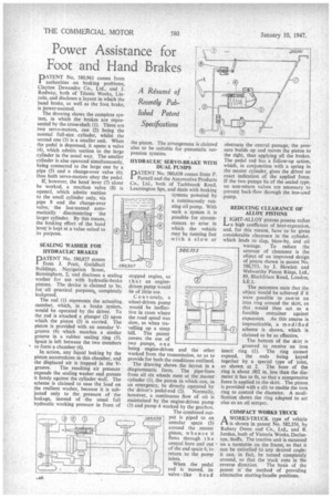
DATENT No. 580,961 comes from authorities on braking problems, Clayton Dewandre Co., Ltd., and J. Rodway, both of Titanic Works, Lincoln, and discloses a layout in which the hand brake, as well as the foot brake, is power-assisted.
The drawing shows the complete syss tern, in which the brakes are represented by the cross-shaft (1). There are two servo-motors, one (2) being the normal full-size, cylinder, whilst the second one (3) is a smaller unit. When the pedal is depressed, it opens a valve (4), which admits suction to the large cylinder in the usual way. The smaller cylinder is also operated simultaneously, being connected to the large one by a pipe (5) and a change-over valve (6); thus both servo-motors obey the pedal.
If, however, the hand lever (7) alone be worked, a reaction valve (8) is opened, which admits suction to the small cylinder only, via pipe 9 and the change-over valve, the last-named automatically disconnecting the larger cylinder. By this means, the braking effort of the hand lever is kept at a value suited to its purpose.
SEALING WASHER FOR HYDRAULIC BRAKES
PATENT No. 580,827 comes from J. Pratt, Guildhall Buildings, Navigation Street, Birmingham, 2, and discloses a sealing washer for use with hydraulic-brake pistons. The device is claimed to be, for all practical purposes,. completely leakproof.
The rod (1) represents the actuating, member, which, in a brake system, would be operated by the driver. To the rod is attached a plunger (2) upon which the piston (3) is carried. The piston is provided with an annular Vgroove (4) which matches a similar groove in a rubber sealing ring (5). Space is left between the two members to form a chamber (6).
In action, any liquid leaking by the piston accumulates in this chamber, and the displaced air is trapped in the V groove. The resulting air pressure expands the sealing washer and presses it firmly against the cylinder wall. The scheme is claimed to ease the load on the resilient washer, because it is subjected only to the pressure of the leakage, instead of the usual full hydraulic working pressure in front of the piston. The arrangement is claimed also to be suitable for pneumatic suspension systems.
HYDRAULIC SERVO-BRAKE WITH DUAL PUMPS
PATENT No. 580,638 comes from F. Parnell and the Automotive Products Co., Ltd., both of Tachbrook Road, Leamington Spa, and deals with braking systems powered by a continuously running oil pump. With such a system it is possible for circumstances to arise in which the vehicle may be running fast with a slow or
stopped engine, so that an enginedriven pump would be of little use.
Conversely, a wheel-driven pump Would be ineffective in cases where the road speed was slow, as when travelling up a steep hill. The patent covers the use of two pumps, o n e being engine-driven and the other worked from the transmission, so as to provide for both the conditions outlined.
The drawing shows the layout in a diagrammatic form. The pipe-lines from all six wheels meet at the master cylinder (I), the piston in which can, in an emergency, be directly operated by the driver's pedal-rod (2). Normally, however, a continuous flow of oil is maintained by the engine-driven pump (3) and pump 4 worked by the gearbox.
The combined out ...580,638 put is piped to an annular space (5) around . the .mastet piston, w hence it flows through the central bore and out of the end space 6, to return to the pump inlets.
When the pedal rod is moved, its valve-like head obstructs the central passage, the pressure builds up and moves the piston to the right, thus applying all the brakes. The pedal rod has a follow-up action, which, in conjunction with a spring in the master cylinder, gives the driver an exact indication of the applied force. If the two pumps be of the sealed type, no non-return valves are necessary to prevent back-flow through the less-used pump.
REDUCING CLEARANCE OF ALLOY PISTONS j IGHT-ALLOY pistons possess rather La a high coefficient of heat-expansion, and, for this reason, have to be given considerable clearance in the cylinder, which leads to slap, blow-by, and oil wastage. To reduce the amount of clearance is the object of an improved design of piston shown in patent No. 580,753, by J. Howlett and Welworthy Piston Rings, Ltd., 89, Blackfriars Road, London, S.E.1.
The patentees state that the object would be achieved if it were possible to cast-in an iron ring around the skirt, as this would then act as a forcible restrainer against expansion. As this course is impracticable, a modifi ed scheme is shown, which is claimed to be as effective. The bottom of the skirt is grooved to receive an iron insert ring (1). The ring cannot expand, the ends being keyed together by a special type of joint, as shown at 2. The bore of the ring is about .002 in. less than the diameter it has to fit, so that a compressive force is applied to the skirt. The piston is provided with a slit to enable the iron ring to control the diameter. A modification shows the ring adapted to act also as an oil scrape!.
COMPACT WORKS TRUCK
AWORKS-TRUCK type of vehicle is shown in patent No. 582,356, by Rubery Owen and Co., Ltd., and R. Jordan, both of Victoria Works, Darlaston, Staffs. The tractive unit is mounted
• on a turntable on the frame, so that it can be swivelled to any desired angle; it can, in fact, be turned completely around, so that the truck runs in the reverse direction. The basis of the patent is the method of providing alternative starting-handle positions.