


Air Exclusion from Hydraulic Braking Systems
Page 36
If you've noticed an error in this article please click here to report it so we can fix it.
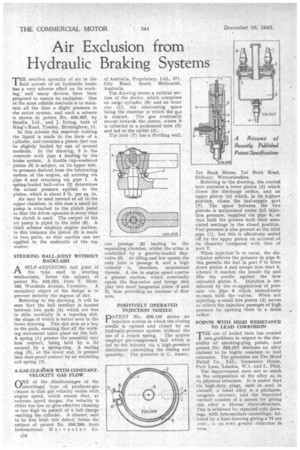
-rim smallest quantity of air in the 1 fluid system of an hydraulic brake has a very adverse effect on its working,' and many devices have been proposed to ensure its exclnsion. One of the most reliable methods is to maintain all the time a slight pressure in the entire system, and such a scheme is shown in patent No. 556,307, by Bendix. Ltd.. and J. hiring, both of King's Road, Tyseley, Birmingham, 11.
In this scheme the reservoir holding the liquid is made in the form of a cylinder, and contains a piston that can be slightly loaded by one of several methods. In the drawing,. 3 is the reservoir with pipe 4 leading, to the brake system. A double cbp-washered piston (5) is subject, on its upper side, to pressure derived from the lubricating system of the engine, oil arriving via pipe 6 and returning via pipe 1. A spring-loaded ball-valve (2) determines the actual pressure applied to the piston, which is about 5 lb. per sq. in.
Air may be used instead of oil in.the upper chamber; in this case a small air pump is attached to the clutch pedal so that the driver operates it every time the clutch is used. The output of the air pump is piped to the inlet (6). A third scheme employs engine suction; in this instance the piston (5) is made in two, parts, so that suction can be applied to the underside of the top washer.
STEERING BALL-JOINT WITHOUT BACKLASH ri A SELF-ADJUSTING ball joint of the type used in steering mechanisms, forms the suhject of patent No. 556,203, • from T. Hirst, 163, Woodside Avenue, Coventry. A secondary object of the design is to prevent entirely the ingress of dirt.
Referring to the drawing, it will be seen that the ball member is honsed between twii pads (4) which are free to slide vertically in a tapering slot, the shape of which is better seen in the lower drawing. This slot acts as a key to the pads, ensuring that all the working movement takes place on the ball. A spring (1) presses the assembly into firm contact, being held by a lid secured by a spring-ring. A sealing ring (3), at the lower end, is pressed into dust-proof contact by an encircling coil spring (2).
A GAS CLEANER WITH CONSTANTVELOCITY GAS FLOW
ONE of the disadvantages of the centrifugal type of producer-gas .cleaner is that gas velocity varies with engine speed, which means that, at extreme speed Mnges, the velocity is either too 16w to give effective cleaning or too high to -permit of a full charge reaching the cylinder. A cleaner, said to be free from this defect, forms the subject of patent No. 556,286, from International Harvester Co. of Australia, Proprietary, Ltd., 171. City Road, South Melbourne, Australia.
The drawing shows a vertical section of the device, which comprises an outgr cylinder (9) and an inner one (1), the intervening space being the chamber in which the gas is rotated. The gas eventually moves towards the centre, where it is collected in a perforated tube (3) and led to the outlet (4).
The inlet (7) has a dividing wall,
one passage (8) leading to the separating chamber, whilst the other, is controlled by a gravity-loaded flapvalve (6). At idling and low speeds the only inlet is passage 8, and a high velocity is, therefore, maintained therein. A rise in engine speed creates a greater suction, which eventually opens the flap-valve and brings into play two more tangential inlets (5 and 2), thus providingan increase of flow area.
POSITIVELY OPERATED INJECTION NOZZLE
PATENT No. 556,140 shows an injection system in which the closing needle is opened and closed by an hydraulic-pressure system without the
use of a return spring. The system employs pre-compressed fuel which is fed tothe injector via a' high-pressure distributor controlling the timing and quantity. The patentee is G. Amery, Tat Bank House, Tat Bank Road, Oldbury, Worcestershire, Referring to the drawing, the central bore contains a lower piston (5) which " closes the discharge orifice, and an upper piston (4) which, in its highest position, closes the fuel-supply port (7). The space between the two pistons is maintained under full injection pressure, supplied via pipe 6, so that both the pistons hold their associated seatings in the closed position. Fuel pressure is also present at the inlet pipe ( 1) , hut this is effectively sealed off by the upper piston on account of its diameter compared with that of port 7.
When injectionns to occur, the distributor relieves the pressure in pipe 6; this permits the fuel in port 7 to force down piston 4 and escape into duct S. whence it reaches the nozzle tip and lifts the needle against the now unloaded piston 5.. Injection is terminated bythe re-application of pressure via pipe 6 which immediately re-seats both the valves. When not injecting, a small free piston (2) serves to relieve the injection passages of high pressure by' opening them to a drain orifice.
POINTS WITH HIGH RESISTANCE TO LEAD CORROSION 'THE use of leaded fuels has created 1 new,problems in respect to the durability of sparking-plug points, and patent No. 556,253 discloses an alloy claimed to be highly resistant to lead corrosion. The patentees are The Mond Nickel Co., , Ltd., Grosvenor House, Park Lane, London, W.1, and L. Pfeil. The improvement rests not so much in the composition of the alloy as in its physical structure. It is stated that for high-duty plugs, such as used in aircraft, a usual alloy is a platinum. tungsten mixture, and the improved method consists of a means for giving this alloy a fibrous' micro-structure. This is achieved by repeated cold, drawings, with intermediate annealings, followed by a final drawing giving a 75 per cent., oi an even greater reduction in area.