


A Variable-speed Gear for
Page 82
If you've noticed an error in this article please click here to report it so we can fix it.
Diesel-engined Vehicles
• A Resume of Recently Published Patent Specifications
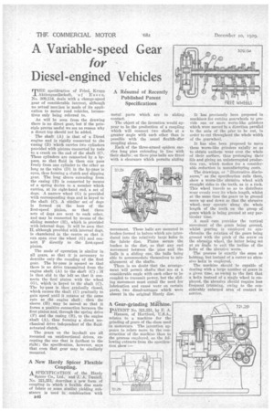
Aktiengesellschaft, of Esse n, No. 309,134, deals with a change-speed gear of considerable interest, although no actual mention is made of its application to motor road vehicles, locomotives only being referred to.
As will be seen from the drawing there is no direct gear, but if the principle proves useful we see no reason why a direct top should not be added.
The shaft (A) is that of a Diesel engine and is rigidly connected to the casing (B) which carries two cylinders provided with pistons conuected by rods to a crank on the end of the shaft -(0. These cylinders are connected by a bypass, so that fluid in them can pass freely from one cylinder to the other so long as the valve (D) in the by-pass is open, thus forming a clutch and slipping gear. The long sleeve extending from the casing (B) is connected by means of a spring device to a member which carries, at its right-hand end, a set of dogs. A narrow wheel (G) is provided with corresponding dogs and is keyed to the shaft (C). A similar sef of dogs is formed on the boss of the first-speed pinion, so that three sets of dogs are next to each other, and may be connected by means of the sliding member (H), which is provided with internal dogs. It will be seen that
although provided with internal dogs, is chambered in the centre so that it can span over the wheel (G) and confleet F directly to -the first-speed The mode of operation is similar in all gears, so that it is necessary to describe only the coupling of the first gear. The by-pass is opened so that there is no drive transmitted from the engine shaft (A) to the shaft (C) ;:H is then slid to the left so that it connects the first pinion with the wheel (0), which -is keyed to the shaft (C). The by-pass is then gradually closed, which causes the shaft (C) gradually to gain speed until it rotates at the same rate as the engine shaft ; then the sleeve (H) may be moved so that it forms a positive connection between the first pinion and, through the spring drive (E) and the casing (B), to the engine shaft (A), thus forming a direct mechanical drive independent of the fluidactuated clutch.
The gears on the layshaft are all mounted on unidirectional drives, excepting the one that is farthest to the right ; the specification, however, says that even thzit gear may be similarly mounted.
A New Hardy Spicer Flexible Coupling. A SPECIFICATION of the Hardy
Spicer Co., Ltd., and J. A. Daniell, No. 321,351, describes a new form of coupling in which a flexible disc made of fabric or some similar yielding substance is used in combination with B46 metal parts which are in sliding contact.
The object of the invention would appear to be the production of a coupling which will connect two shafts at a greater angle with each other than is possible with the usual flexible-disc coupling alone.
Each of the three-armed spiders carries long pins extending in line with their shafts ; on these pins halls are fitted with a clearance which permits sliding movement. These balls are mounted in bushes formed in halves which arc introduced into the relatively large holes in the fabric disc. Plates secure the bushes in the disc, so that any end movement between the •pins and the balls is a sliding one; the balls being able to accommodate themselves to misalignment of the shafts.
There is 1130 doubt that the arrangement will permit shafts that are at a considerable angle with each other to be coupled to transmit power, but the sliding movement must entail the need for lubrication and cause wear on certain parts, two disadvantages which were absent in the original Hardy disc.
A Gear-grinding Machine.
pATENT No. 321,251, by E. A. Hanson, of Hartford, U.S.A., relates to a machine for the grinding of gears of the class used in motorcars. The invention appears to relate more to the construction of the machine than to the process employed, as the following extracts from the specification show :— It has previously been proposed in machines for cutting gearwheels te provide one or more worm-like grinders which were moved hi a direction parallel to the axis of the gear to be cut, in order to cut throughout the whole width of the gearwheel.
It has also, been proposed to move these worm-like grinders axially so as to obtain uniform wear over the whole of their surface, thus prolonging their life and giving an uninterrupted production run, which makes for a considerable reduction in manufacturing costs.
The drawings, or " illustrative disclosures," as the specification calls them, show a -worm-like abrasive wheel with straight sides to the teeth, as in a rack. This wheel travels so as to distribute wear evenly, over its whole length, whilst at the same time the gears to be ground move up and down so that the abrasive wheel may operate along the whole length of the teeth on the group of gears which is being ground at any particular time.
A snail cam provides the vertical movement of the gears being ground, whilst • gearing is employed to synchronize the rotation of the gears being around with. the pitch of the screw on the abrasize wheel, the latter beina' set at an angle to suit the incline of the helix of the abrasive worm.
The process is exactly the same as hobbing, but instead of a cutter an abrasive helix is employed.
The machine should he capable, of dealing with a large number of gears in • a given time, as owing to the fact that -a helix instead of a single wheel is employed, the abrasive should require less frequent trimming, owing to the Con-siderably enlarged area of contact in service.