


Patents Completed.
Page 18
If you've noticed an error in this article please click here to report it so we can fix it.
iCornplete specifications of the following patents will be sent to any address in the United Min gdont upon receipt of eightpence per copy at the Sale Branch, Patent Office; Holborn, W.C.
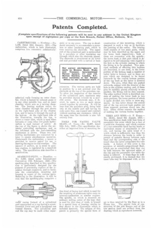
CARBURETTER. — Mowbray.—No. 1,140, dated 16th January, 1911.—The carburetter, which is here illustrated, comprises two concentric substantially spherical walls forming an outer chamber, which is heated by exhaust gases or in any other suitable way, and an inner chamber which acts as a mixing chamber. The heating medium enters the outer chamber through the port shown on the right-hand side of the illustration, and it leaves it through the port at the bottom. At the right-hand side of the illustration, towards the top, is shown a water inlet, which is used when kerosene or some other low-grade hydrocarbon is used instead of petrol. At the top of the figure is shown the airintake controlling mechanism, and on the left-hand side the fuel-controlling mechanism is shown. These two controlling mechanisms are connected by a lever to ensure simultaneous operation. Underneath the carburetter, a saucer is provided to receive petrol for use Ar starting the engine in cold weather. The amount of suction, as is usual in gasolene engines, is regulated by a manifold valve. The specification also describes a modification.
SPARKING-PLUG. — Mazellier. — No. 3,559, dated under International Convention 17th February, 1910.—The sparking-plug described in this specification is particularly designed for the purpose of preventing rupture of the insulator through expansion, and to facilitate the construction, mounting and keeping in repair of the various parts. Referring to the illustration, it will he seen that the sparking-plug comprises a inetF casing formed of a cylindrical part superposed on a cup having a screwthreaded lower end and a hexagonal nut formed thereon. The cylindrical part and the cup may be made either senor ately or in one piece. The cup is shouldered internally to accommodate a porcelain or other insulating part, which :n turn receives the electrode. The upper end of the cylindrical part is surmounted by a porcelain or other insulating cap through which also the electrode passes. The electrode is shouldered at its lower end and provided with a curved or bent
extension. The various parts are held in position by a nut screwed over the electrode at the top of the porcelain cap. To allow for inspection of the interior of the cylindrical part, apertures may he provided therein covered by a movable screen. The electrode may, if desired, be made in two or more pieces joined together by screwing. It will be seen that, the porcelain plug, being held only at the middle part and having its ends quite free, can expand and contract without meeting any resistance, while at the same time the electrode is also 'eft entirely free.
TOOLS FOR FACING VALVE SEATS.—F. Tvers.—No. 16,607, dated 12th July, 191d.—This specification describes an improved form of mounting for that kind of facing tool which is used for the recutting of mushroom-valve seats on internal-combustion or similar engines. The spindle, on which is mounted an ordinary milling cutter of the type that is used for this class of work, is housed in a special form of bearing, similar to that shown in the illustration which is included herewith. The subject of this patent is primarily the special form of construction of this mounting, which is designed in such a way as to facilitate the centring of the cutter. The bearing itself consists of two main parts, which may be here described as the upper and the lower bush respectively; both of these are concentric with the spindle ; the lower bush is that part which is designed to be self-adjusting with regard to the hole in the cylinder casting to which the fitting is to be attached. Two principal methods of effecting this location are described, in one form, in the lower portion of the bottom bush a number of radial holes is formed, and in these are pins which are designed to be forced outwards by the conical bottom portion of the top bush as the latter is screwed down. The pins, when they are pushed outwards, engage with the interior of the hole in the cylinder casting, and, if these pins be suitably placed relatively to one another, the fitting will he duly centred. The other method which is described consists of making the lower bush in two main portions, the lower portion of which is again divided into three or more segments. In this latter design the conical end of the top screwed bush pushes out these separate portions direct into the hole. Other claims concern the method of holding the various bushes together_ TIRES AND RIMS_—A. F. Evans.— No. 18,611, dated 6th August, 1910.— This specification deals with that form of pneumatic tire cover which has a face of a solid-tire character, and which consists of a non-extensible band having beads or equivalent means of attachment to the rim, and having the solid tread of a width which is sufficiently less than the distance between the beads in order to permit of suitable flexure between each bead and the corresponding side of the tread when the latter compresses the tube
inside. A feature of this cover is the provision of suitably-proportioned flaps, which are so constructed that they can be held between the upturned edges of the rim and the pneumatic tire when the latter is inflated. If these flaps be sufficiently prolonged, it is claimed that the inner tube may he dispensed with, as the air is then retained by the flaps as in a Fleuss tire. The special form of construction 'of the side flanges and of the tire section itself are evident from the drawing which is reproduced herewith.