


SIMPLE MECHANICS
Page 41
Page 43
If you've noticed an error in this article please click here to report it so we can fix it.
by Preceptor
Steering geometry 1.
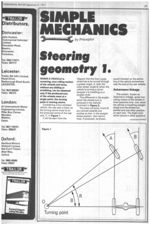
WHEN A VEHICLE is cornering, true rolling motion of the wheels and tyres, without any sliding or scrubbing, can be obtained only if the produced axis of the wheels meet at a single point: the turning point or turning centre.
Considering a four-wheeled vehicle, the rear axle is fixed, so the turning centre must lie on the produced centre of the rear axle, 0, in Figure 1.
It will be seen from the diagram that the front inside wheel has to be turned through a greater angle, A, than the outer wheel, angle B, when the vehicle is turning a corner because it is travelling on a smaller circle.
This difference in the angles which the wheels turn is achieved in the manner illustrated in Figure 2.
The track rod arms, A and B, are inclined towards one another so that, in the straight ahead position, their centre lines, if produced, as shown, would intersect on the centre line of the vehicle somewhere near the axis of the rear wheels.
Ackermann linkage
This system, known as Ackermann linkage, gives true rolling motion of the wheels in three positions only: one, when the vehicle is travelling straight ahead and the wheels are parallel and one other position on each lock. The slight error which occurs in other positions
is neutralised by the flexibility of the tyres.
A line diagram showing how the different angles through which the wheels are inclined on a corner is reproduced in Figure 3.
In this case, the steering is shown on a right-hand lock and it will be seen that the offside wheel, which, in this case, is the inner wheel on the corner, is turned through a greater angle "B" than the nearside one (angle -A").
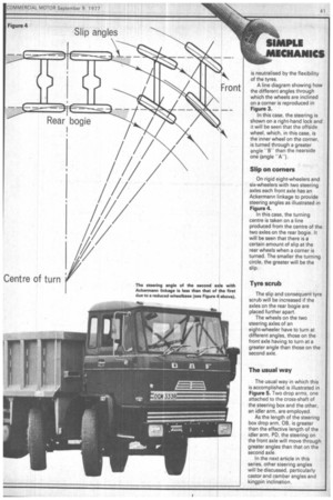
Slip on corners
On rigid eight-wheelers and six-wheelers with two steering axles each front axle has an Ackermann linkage to provide steering angles as illustrated in Figure 4.
In this case, the turning centre is taken on a line produced from the centre of the two axles on the rear bogie. It will be seen that there is a certain amount of slip at the rear wheels when a corner is turned. The smaller the turning circle, the greater will be the slip.
Tyre scrub
The slip and consequent tyre scrub will be increased if the axles on the rear bogie are placed further apart.
The wheels on the two steering axles of an eight-wheeler have to turn at different angles, those on the front axle having to turn at a greater angle than those on the second axle.
The usual way
The usual way in which this is accomplished is illustrated in Figure 5. Two drop arms, one attached to the cross-shaft of the steering box and the other, an idler arm, are employed.
As the length of the steering box drop arm, OB, is greater than the effective length of the idler arm, PD, the steering on the front axle will move through greater angles than that on the second axle.
In the next article in this series, other steering angles will be discussed, particularly castor and camber angles and kingpin inclination.