


Progress in Two-stroke Oil Engines
Page 58
If you've noticed an error in this article please click here to report it so we can fix it.
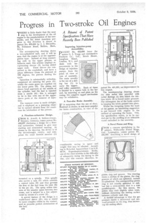
'THERE is little doubt that the next 1 step in the development of the oil engine is the popularization of the two stroke, and the latest American progress in this direction is shown in patent No. 452,444 by J. J. McCarthy, 91, Fellsmere Road, Malden, Mass., U.S.A.
The accompanying drawing shows a two-cylindered unit, and it will be seen that the engine is of the opposed piston type. Instead of long connecting rods to the upper pistons, as hitherto used, this scheme employs re ciprocating sleeves (2) having closed upper ends. These sleeves are con nected to the crankshaft, and have a phase difference (from the pistons) of 170 degrees, the pistons leading the cycle.
Operation is substantially orthodox, compresed air entering the ports (1), whilst the waste gases are expelled via the lower ports (3). The piston and sleeve head approach at the middle of the cylinder, and the fuel is injected from a nozzle (4) ; this is arranged to be in line with one of the uppersleeve ports at the moment of injection.
The topmost cover is made airtight, and is employed as a pumping chainber to extract oil-mist from the crankcase for lubrication of the pistons.
A Floaffess-carburetter Design.
FROM R. Arnold, 6, Schloss-strasse, 11Dresden, Germany, comes patent No. 452,377 disclosing a design for a float. less carburetter, claimed to give easy starting and economical running. As shown in the drawing, the device is of the downdranght variety, and comprises the usual throttle member (1)
mounted on a spindle. This spindle also carries a cam (7) which controls a conical valve (6) and thus governs the flow of the fuel from the inlet (5) to the jet (4). The spray orifice consists of the annular space between two cones, and is subject to a fine adjustment by means of a screw (3).
A special feature of the design is a multi-bored sleeve (2) ; this is stated to cause complex eddies in the venturi, and so promote perfect atomization of the fuel.
B24 Improving Injection-pump Accessibility.
PATENT No. 452,609 bears the names G. J. Trapp and Automotive Products Co., Ltd., Brock House. Langharn Street, London, W.1, and deals with improvements in the design of injection pumps, from the point of view of ease of assembly. The main novelty is the use of a sliding bar (1) to carry the tappetand roller asgemblies. Each of thece is located in a square bole in the bar and, by removing an end plate on the casing, the complete tappet mechanism may be withdrawn.
A Face-disc Brake Assembly.
I T is surprising that the use of discs, instead of drums, is not more popular . for brake construction, in view of the considerable, saving in space • and weight that may be effected. According to Rotadisk Apparatebau G.m.b.H. 63-74, .Kopenhagenerstrasse, Berlin, one of the chief troubles is the difficulty of adequately fixing the facing to the disc, and this concern describes, in patent No. 451,551, an improvement in this respect.
The accompanying drawing shows the thin metal disc provided with radial flutings (1) into which the friction fabric (2) is forced under pressure. The subsequent use of the brake assists in keeping the fabric pressed into place.
Whilst the foregoing forms the basis of the patent, an interesting suggestion is put forward with respect to the method of operating the brake. This, the specification states, is to be carried out by the swelling of an inflatable vessel embodied in the assembly.
A Novel Piston and Ring.
FROM a concern specializing in the subject, Wellworthy Piston Rings, Ltd., Lymington, comes patent No. 452,057, describing a novel design of
piston ring and groove. The drawing shows a section of the piston, the ring. grooves of which are spherical, instead of cylindrical. The corresponding piston ring is not exactly spherical to suit, but has a, cross-section that is a true parallelogram. By this means, the piston may rock slightly when worn, without disturbing the mating surface between cylinder and ring.
A further advantage is that the gas pressure exerts a downward and outward pressure on the ring, thus increasing the sealing effect.