


Sliding-wedge-operated Brake Gear
Page 42
If you've noticed an error in this article please click here to report it so we can fix it.
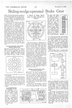
A Réwnil of Patent Specifications that Have Recently Been Published AN improved brake-drum assembly is shown in patent No. 571,562, by W. and C. Colebrook, 52, Heyshott Road, Southsea, Hants. The mechanism is of the type in which the shoes are spread by sliding wedges.
Referring to the drawing, the shoes are constrained to a linear path, being guided by slots (I) which slide on pins projecting from the back plate. Each shoe is fitted with anti-friction rollers (2), which bear on top and bottom wedge-members (3 and 4). These are mounted on a frame which slides as a -whole, and, when moved upwardly, uniformly spreads both ends of the shoes. The operating mechanism is also a sliding wedge; this lies at right-angles to the backplate and is contained in the housing (5). The adjusting means consist of a screw-and-nut coupling between the cam-follower and the frame, the head of the screw being formed into a pinion so that it can be turned, via a crown-wheel, from an easily accessible point.
A QUICK-CHANGE TRACTORWHEEL MOUNTING D APID adjustment of track width is
the object of a design for a tractor hub shown • in patent No. 571,511, by E. Allman Elmstead Birdham Road, Chichester, Sussex. The hub will give two widths of track, whilst, if offset wheels be also employed, two more will be available.
The drawing shows the proposed hub, which is fitted with two spaced flanges to. give the two widths. Each flange is of " hilt-and-dale " outline, so that the wheel may be passed over one to reach the other. The number of flanges is not limited to two, but may be extended to cover as many different widths as are needed.
AN INTERESTING VARIABLE GEAR
AVARIABLE gear
which, although employing friction, applies it in a very practical manner, is shown in patent No. 571,499, by Graham Transmissions Inc., Milwaukee, Wisconsin, V.S.A. The patent is actually concerned only with a part of the gear— a univeral joint.
The drawing shows a half-section of the gear, the rotational axis being situated at a point a little below the lower edge of the drawing. The input shaft drives a rotary carrier (1), which has mounted upon it a number of planetary taper rollers (2). These are journalled at one end in blocks (3), which can • slide outwards under the influence of centrifugal force. The other end is universally jointed to a planetary gear (4), which drives the output member, consisting of an internal gear (5).
Variation of ratio is obtained by sliding an outer race (6) along the rollers, so that it makes contact with them on a different diameter. The working pressure between rollers and race is created by some convenient method, possibly springs, but under load the pressure is increased by the Centrifugal action of the bearing blocks (3).
IMPROVED RIVETING FOR CLUTCH FACINGS
PNo. 571,573 comes from H. Barker, and Borg and Beck, Ltd., both of Tachbrook Road, Leamington Spa, and discloses an improved method for riveting on the friction facings of
clutches and the like. Because the thickness is limited, the chief problem is to find space for the rivets without incurring the risk of their heads scoring the steel plates.
Referring to the drawing, it will be seen that each rivet secures one side only of the friction facing. For example, the upper riyet holds the facing (1), whilst its other end holds a thick washer (2) on to the steel plate. But although this washer does not grip the. right-hand facing, it provides, nevertheless, valuable support thereto in the direction of loading, acting as a rigid key. but occupying little thickness. The lowermost assembly is similar, but is reversed in a left-to-right direction AN INJECTION-PUMP GOVERNOR
AGOVERNOR intended for use with engines employing fuel injection, form the subject of patent No. 571,408, from G. Green and Wyndham Hewitt, Ltd., Lagonda Works, Staines, Middlesex. The device is claimed to give stable governing over a wide speed range without the need for artificially modifying any of its natural characteristics.
The drawing gives a diagrammatic view of the apparatus used, which corn prises an engine-driven pump (1) that forces fluid around a circuit containing a restricting orifice (2) and a springloaded release valve (3) leading back to the supply. A branch pipe on the pressure side leads to a cylinder (4), the piston in which is responsible for operating the rack-rod of the injection pump.
The novelty of the system lies in the design of the restricting orifice and its housing; this is arranged so as to, create turbulence in the passing fluid, and so produce back-pressure proportional to the square of the engine speed. By adjusting the pressure of the releasevalve spring (5), the vertex of the characteristic curve can be moved to a new value, but its form remains parabolic.