


Patents Completed.
Page 22
If you've noticed an error in this article please click here to report it so we can fix it.
A Four-wheel-drive System. Combined Friction and Chain Driving. A Nonslipping Wheel Sheath. A New Feather Key.
Copies of complete specifications of the patents published on this page can be obtained from the Sales Branch, Patent Office, Holborn, W.C„ at the cost of .sixpence for each specification.
J. G. P. Tnosias, No. 12,949, dated 9th September, 1915. —This invention is part of a system of transmission in which all four wheels of the vehicle are driven. The engine drive first passes through an epicyclic gear and two electrical machines, dealt with in previous patents. The present patent deals with the gearbox and axle-driving shafts, shown in two horizontal sectional drawings. The drive enters the gearbox by the small sun-wheel on the left of the first drawing and pa.sses through the planet gears and large sun-wheel to the sliding gears. Normally the small sun-wheel dives both sliding gears and therefore both driving shafts, the latter in either direction as required. In this .action the planet carrier is rotating, both sliding gears are in mesh and all the four vehicle wheels are directly driven. The double planetary gear allows a differential movement as between the driving shafts for each side of the vehicle. Each driving shaft contains a differential gear, shown in the second drawing, acting between the front and rear wheels. Each sliding gearwheel is capable of meshing with a wheel on either driving shaft, thus providing a reverse drive, and also of a neutral position. The invention also provides an over-all change of speed, apart from. the usual change-speed gear, to suit the case of a vehicle returning light after drawing a heavy load.
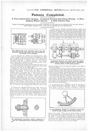
W. SKA1FE, No. 101,460, dated 8th June, 1916.—The invention is a key or feather for connecting three concentric pieces. The key is in the form of an inverted T, the crosspiece fitting into the solid shaft while the stem passes through a slot in a sleeve shaft and projects sufficiently to enter the key-way of a wheel or clutch member. It is shown in crosssection in position, the outer dotted circle representing a wheel. H. SEABITRY, No. 101,436, dated 2nd February, 1916.—This invention combines friction and chain driving, giving three speeds and a complete reverse drive at the same speeds. The drawing is a plan view. The main shaft is in two parts working co-axially; at the left side is the end of the engine shaft, carrying a drum; next a shaft carrying a friction pulley indicated inside the drum and extending to the second coned friction outer member ; the third extends from the inner cone
friction member to the universal joint thence to the differential of the vehicle.
The engine shaft drum has friction surfaces both inside and out and drives the main shaft from the inside surface. The sprocket wheels are put into action by the friction members giving a direct medium, and geared high and low speedi as lead successively from left to right on the drawing, the countershaft being used to transmit the high and low speeds. To reverse the direction of drive on the vehicle axle the whole gear is swung back in relation to the drum on the engine shaft. 13,y this movement the engine-shaft drum is freed from the friction pulley on its inner surface and brought into contact, on its outer surface, with the pulley on the lef thand end of the eountershaft.
D. M. MACFARLANE, J. ANDERSON and G. H. ROBERTSON, No. 13,289, dated 17th September, 1915.—A non-slipping wheel sheath is made of cross-bars connected in chain-link fashion into a belt. When not in use the sheaths are held flat out on platforms at each side of the car. When required the 'sheath is lowered off_ the platform and strapped round the wheel. A small windlass is mounted on the platform for lowering off the sheath and hauling it back. The drawing shows part of a wheel with the non-slipping sheath in posi• tion for work connected at the ends by clamps.