


Abridgments of Interesting Patent Specifications.
Page 20
If you've noticed an error in this article please click here to report it so we can fix it.
Boring Tool ; Governor; Controlling Device ; Valve Mechanism.
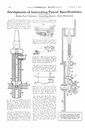
No. 29,600A, dated December 3tst, ioe4. —Boring Tool.—Walker.—•For boring boiler tube-plates in such a manner that a recess, in the thickness of the plate, is formed, into which the tube can be expanded by a tool (f), having two cutters (c). Each cutter has a recess which engages a worm (et) on an operating rod
(e). The rod (e) is controlled by a cane (g), and when the tool has entered the plate (1) a sufficient distance the cam is operated so that the cutters advance at right angles to the tool, and cut the recess and bevel as required. The shape of the boring is shown on the right-hand of the figure, although this is not cut to its full depth.
No 26,592, dated December 6th, 1904.— Governor for Steam Engine.—The Warwickshire Machinery Co., Ltd.—This is an emergency governor for shutting off steam when a given speed limit is reached. To the engine shaft a plate (i1) is bolted, and pivoted thereon is a lever 05) controlled by a spring (19). Pivoted in prox
imity to the -lever (is) is a tripping lever (13). The two levers ate provided with opposed recesses to receive a link (14).
The lever (13) is weighted as shown at (13a), and when a given speed limit is reached the centrifugal action, upon the weight overcomes the pull cf the spring, so that the weight flies out and strikes a plunger (to). The plunger by means of levers (6), (7), and (8) releases a weighted arm (4), which in turn strikes an arm (3) on the spindle of a butterfly valve (2). Steam is thus instantly shut off.
No. 3,697, dated February 22nd, 1905. —Control Device. Munro.—The lever (a) is controlled by the governor of the engine, and by means of a Bowden wire (b) sliding in the casing (g) operates the lever (c) of the spring-controlled
throttle valve (c.1). One end of the Bowden casing (g) is fixed at e, but the other end is secured to a lever (II). The lever (h) may be operated by a second Bowden wire 0) and spring (k), either to the left or right, for the purpose of throttling, irrespective of the governor.
No, 25,814, dated March 28th, 5904.— Valve and Ignition Mechanism.—Altree. —The valve (j) is operated by a tappet (F) sliding in a member (G) pivoted at H to the frame of the motor. The member ((3) also carries a guide piece (D) engaging a cam-groove (C) in the face of a drum (B) fast on the engine shaft (A). On the inner side of the drum (13) is a cam (E), and the groove in the drum is so shaped that the member (F) is brought over the cam at the moment when the valve (I) is to be opened, but at other times is moved to the right of the earn, so that no operation of the valve takes place. The member ((3) also carries a wiper or brush (P), which, when the guide piece (D) is at the far side of the drum (B), comes into contact with a contact piece on a disc (R), whereby ignition is effected.