


Safety for Hydraulic Servo Brakes
Page 72
If you've noticed an error in this article please click here to report it so we can fix it.
ACONTROL valve for a hydraulic servo brake forms the subject of patent No. 791,257. (Fodens, Ltd., E. Twemlow and J. Mills, all of Elworth Works, San dbach, Cheshire.) Its chief feature is the means used to operate an emergency brake if the hydraulic power should fail.
A pump (1) circulates fluid through a cylinder (2) containing a hollow piston (3). As the piston is normally at the right-hand end of its cylinder, the fluid can escape back to the reservoir only by opening a valve (4) in a central bore.
When the pedal (5) is depressed, a crank-arm (6) closes the valve through springs (7) and so creates a pressure in the circuit which reaches the brakes via the pipe (8). The greater the pressure generated, the greater is the force on the pedal, so that the driver can feel the reaction.
In normal use, the movement of the valve is very small, but should the hydraulic supply fail, both the valve and the hollow piston would be forced leftwards. The excess movement causes the pedal crank-arm to meet an abutment (9) carried on a lever (10). This is externally connected to an emergency braking system of which no details are given.
A CROSS-ROLLER REARING MORMAL types of roller bearing do i not resist end-thrust and can in fact be slid completely apart in an endwise direction. A bearing in which the rollers are positively located axially is shown in patent No. 792,037. (British Timken, Ltd., 65 Cheston Road, Aston, Birmingham, 7.)
The outer race is in onc piece and is machined in the form of a V:groove (1). Two sets of rollers are used, inclined atopposite angles, as shown at 2 and 3. The inner race is also V-grooved, but must be divided to permit assembly; it consists of two separate rings each ground to an angle suitable for one set of rollers.
The cage (4). is in one 'piece and is 'milled out to form tapered pockets to suit the-form of the rollers. The pockets , ate rather more than a semi-circle so that the rollers are prevented from falling out. The method of milling the pockets is described in detail and forms part of the patent. References are made to two earlier patents numbered 689,281 and 703,036.
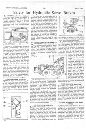
AN AMERICAN DUMPING TRAILER A FRAMELESS trailer intended for r-trearward dumping is ,shown in patent No 791,840. (Athey products ,Corp.„ 5631 West 56th Street, Chicago, Illinois, U.S.A.) The machine is hailed. by a_ two-wheeled tractor and steering is performed by articulation between the tWo_ sections.
The drawing shows the general outline of the composite vehicle. The two units are united by a king-pin and provision is also made for 'relative _up-and-down deflections. The steering is poweroperated, a hydraulic ram cylinder (I) being provided between the gooseneck and the tractor.
Tipping is performed by other hydraulic rams (2); these are of the multistage type to obtain the required length of stroke. As a safety stop to the tipping movement, a limit cable (3) is provided. The body portion is pivoted for tipping at points at the end of the side-arms (4) and the road wheels move forwards slightly as tipping progresses.
NOVEL ENGINE-WARMER !MAINS-ENERGIZED engine-warmers are often made in the form of an immersion heater which has to be specially fitted into the water jacket. A scheme in which the iron of the casting itself forms the heater unit is shown in patent No. 792,319. (Power Frequency Heating, Ltd., Peregrine Works, Larnpton Road, Hounslow, Middx.) Not only is the engine kept warm, but the battery is charged as, well; this is because the heater unit lends itself readily to the incorporation of a rectifier. —. A mains-connected transformer is wound on a set of E-shaped laminations (1). To complete the magnetic circuit, the ends of the E must be connected by iron, and this is achieved by placing it against the iron of the, cylinder-block, where, it adheres by magnetic attraction. As the iron of the block is not laminated, hysteresis losses and eddy current" losses occur, and these appear ' as heat in the jacket, so setting up the warming action.
The transformer is also provided with a. lowvoltage winding, the output of which is'led to a rectifier (2), arid -the resultant d.c. • is used to charge the battery. A pilot light (3) shows when, the unit is energized. The item shown at 4 is described as "an additional resistive load" but no details are given as to its purpose. The patent also covers a form of thermostatic control for the unit.
ENGINE-KNOCK ADDITIVE
PATENT. No,. 792,704 deals with a I method of treating fuel to improve its anti-detonating properties. An additive is made by reacting an organic carboxylic acid with lead, copper and zinc. The quantities of copper. and zinc required are quite small; and it is thought sufficient to pick them up from the brass cocks and coprier pipe through which the fuel flows. (E. Drouven, Torndel Benaco, Verona, Italy.)
KEEPING STONES OUT OF TWIN TYRES
STONES often lodge between the two tyres of a twin wheel and may cause damage to the side wails. To prevent this, patent No. 791,279 proposes to place ametal disc between the two tyres to discourage the entry of stones, also to act as a centrifugal fan to circulate cooling air. The disc is provided with a corrugated periphery to assist this action. (L. Allen, Shelley Court, Lovelace Road, Surbiton.)