


For DRIVERS, MECHANICS & FOREMEN.
Page 21
If you've noticed an error in this article please click here to report it so we can fix it.
A PRIZE OF TEN SHILLINGS is awarded each week to the sender of the best letter which we publish on this page ; all othere are paid for at the rate of a penny a line, with an allowance for photographs. All notes.are edited before being . published. Mention your employer's name, in confidence, as evidence of good faith. Add/ress, b., M. and F„, " The Commercial Motor," 7-18., Itosebery Avenue, London, E.C. 1.
Light your lamps at 9.6 in London, 10.9 in Edinburgh, 9.28 in Newcastle, 9.26 in Liverpool, 9.17 in Birmingham, 9.16 in Bristol, and 10.3 in Dublin.
Lamps Alight—
A Simple Cylinder Grinding Attachment for an Engine Lathe.
The sender of the following communication has been awarded the Ws. prize this week.
[1851j " 11.3.1." (West Broanwieh) writes :—" The other day I came across a most ingenious contrivance for grinding petrol engine cylinders. It was fitted to an ordinary engine lathe in a garage, and I think the
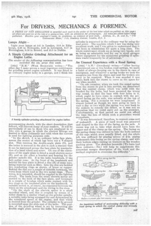
A handy cylinder-grinding attachment for engine lathes. accompanying sketch, with the short description that 'follows, will interest many of your readers. It will be
particularly of use to those who are employed in or who own a garage in which the electric fittings are limited to those ordinarily met with when the current is used for lighting purposes only.
" In the sketch, A is an ordinary lathe face plate, across the centre of which 1132been cut a V-shaped slot. This receives the double-angle plate (D), and the latter is secured in the slot in such a wanner that it can be traversed across the face plate by manipulation of a hand wheel and screw. On one of the extensions of the angle plate is fitted a small electric motor (E), and on the other a bracket and bearing for the grinder spindle (G). B is the lathe headsto-ck, G the belt pulley cone. At the front of the headstock and behind the face plate is fitted a disc (H) of SOLfre insulating material such as fibre. Into, the disc are bedded two conducting rings as shown, of brass or copper. Behind the disc are a couple of suitabla terminals, the wires from which lead to the two metal rings. These wires, it is intended, should be coupled to the lighting circuit. The leads from the small electric motor are carried to the back of the face plate, and terminate in a couple of brushes which make contact with the two rings on the insulated plate on the headstock. A suitable switch is, of course, incorporated between the wires on the attachment and the wiring in the shop. " On the shaft of the electric motor is 8, small sprocket wheel, and this is coupled by means of a roller chain to a similar wheel on the grinder spindle, a suitable ratio being arranged for and determined by the rotational speed of the engine, and that which is desired from the grinder. The cylinder to be ground is mounted upon the slide rest of the lathe. The position of the grinding wheel is set by traversing the double angle plate across the lathe face plate. The
cylinder is traversed in the ordinary way by using the lead screw. The machine whichI saw was doing very excellent work, and I was given to understand that it had been in commission for quite a long time. The whole contrivance struck me as being very handy, and as being an admirable tool for use in small garages where equipment for the occasional grindink of cylinders wauld frequently be of advantage."
An Unusual Experience, with a Road Spring.
[1855] " AM," (Dewsbury) writes :—" After having experienced one or two broken road springs, we made a habit of always keeping one in the stores in case of emergency, and whenever a spring broke we took the complete one from the stores and sent the broken one away to be repaired. When it was mended it was taken back into the stores to serve as the spare for use when needed. •.
"On ode occasion, when We took the sound spring from the stores to put it into service, we discovered that the central clamp, which was solid. with the bracket for the bolts, had been mounted the wrong way round, so that the base with four holes in it, which ought to have come in contact with the pre-pared facing on the axle, was actually at the top of the spring.. For a moment we were nonplussed. it Almost looked as though we were going to have to wait a day or two while the spring was sent back to the makers to remedy the defect, as it was not an alteration that we Could carry out on the premises. Unfortunately, at that period we could not afford the time the loss of which such aprocedure would necessitate. " It was determined therefore, to concoct some sort of makeshift. A piece of hard wood was Procured and shaped to the size of the facing. on the axle. A recess was cut to take what should have been the upper end of the clamp on the spring. The facing on the spring clamp was utilized to take the bolts instead of the caps which were usually fitted, and the whole job was stiffened by placing -pieces of fin, piping underneath this facing on the spring clamp,and with their bottom edges resting on washers on the wooden packing piece. The sketches herewith We have had them redrawri.a).] will help to supplement this somewhat meagre description of the workand the method employed to overcome the difficulty."