


Springing on Tandem Rear Axles
Page 94
If you've noticed an error in this article please click here to report it so we can fix it.
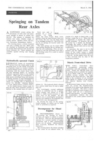
A SUSPENSION system giving the (-1 advantages of both steel and pneumatic springs is shown in patent No. 881,163. The scheme is intended for tandem rear axles, whether singly or doubly driven. (Rubery Owen and Co., Ltd., 'Darlaston,. Wednesbury, Staffs.) The drawing shows a driven foremost axle and a trailing rear one. Both axles are attached to laminated steel springs (1) having their forward ends pivoted on frame brackets (2). These position the assembly against driving and braking torque.
Hydraulically operated Clutch
HYDRAULIC means of transmitting motion from the clutch pedal to the operating lever on the clutch cross-shaft is frequently found on modern vehicles. A recent Dunlop patent reveals means of dispensing with the clutch thrust bearing and operating fingers, by carrying hydraulic operation direct to the friction surfaces. With such an arrangement, at high speeds centrifugal force can increase hydraulic pressure so that disengagement is impeded, if not actually prevented. A means of avoiding this is disclosed in patent No. 881,948. (Dunlop Rubber Co., Ltd., Albany. Street, London, N.W.1.)
In the clutch shown, friction pads (1) grip the disc when hydraulic pressure is a•pplied to the outside faces of a pair of
pivoted on a cross01,163. member (3) lying below the main frame. Both crossmembers have air bags between them and the frame, the rear one (4) being fixed to an outrigger bracket (5). The front one has its air springs (6) located under the main frame.
The steel springs can be made stiffer than normal because the air springs provide the soft, Cushioning. They are pressurized to suit the prevailing load and a self-levelling valve (7) is used to control the pressure.
pistons (2). The hydraulic fluid is ducted via a central shaft bore (3) and a radial pipe (4),
The centrifugally created additional pressure is cancelled out by a springloaded plunger unit shown at 5 that applies a slight counter-pressure to the inside faces of the pistons. As this pressure, too, is centrifugally increased it opposes that induced in the hydraulic line and permits easy disengagement.
By altering the mass of the springloaded plunger, its action can be made small or powerful as required,
Decompressor for Diesel Engines
AA DECOMPRESSING device for f-k assisting the starting of directinjection oil engines is shown in patent No. 882,033. Once set, the decompressor operates for a certain number of engine revolutions and is then automatically thrown out of action. (Motorenfabrik Hatz G.m.b.H., Ruhstorf bei Passau. Germany.) The drawing shows the device attached to the rocker ef an exhaust valve. It consists of a shaft (1) fitted with a cam having a single flat on it. When the flat is uppermost, it permits the rocker tc operate normally. If, however, the cam be turned by a handle •(2) through a right-angle, the rocker is lifted enough to open the exhaust valve and so ease the compression.
In operation, the cam is set in this position and the engine rotated. Each stroke of the rocker causes a simple ratchet-wheel (3) to be notched round by a pawl (4). As the engine turns, the cam is thus returned step by step to the inoperative position.
Morris Front-wheel Drive
THE B.M.C. front-wheel drive
• arrangement, comprising engine, transmission and axle assembly, is well known. Patent No. 881,998 states that the existing layout is suitable for engines of up to about 1,500 ex., and shows a modified version suitable for larger engines of two litres and over. The chief point is the avoidance of alt overhung clutch which is a feature of the smaller unit. (Morris Motors, Ltd. Cowley, Oxford.) In the present larger version, the crankshaft (1) carries the flywheel-clutch assembly (2) as close to the adjacent main bearing as possible. The drive is taken through an outboard train of gears (3) to the input shaft (4) of a conventional layshaft-type gearbox. In other respects, the transmission follows the lines described in the earlier patent numbered 832,004.