


Commercial-vehicle Petrol Engines.
Page 19
Page 20
If you've noticed an error in this article please click here to report it so we can fix it.
[A further instalment of Mr. Williamson's paper on 'Commercial-vehicle Engines." appears below, in continuance from page 16 in our last issue, We have adopted the policy of reproducing this monograph in small doses largely on account of the somewhat technical nature of its contents and our desire to render these, as Jar as possible, palatable to as large a number of our readers as possible. We are reproducing a further number of
drawings which are of moment in this •connection.—ED.]
We concluded the instalment, in last week's issue, of the paper by Mr. Williamson with the reproduction of the valve diagram, which he presented as representing the average valve setting as approximated on a number of established commercial-vehicle-engine designs.
Pistons.
Proceeding, the author had a few words to say about pistons, and he voiced his preference for that type of piston which is known as the Zephyr patent. There is certainly much to be said for this design, in that it obviates the necessity for a scraper ring, and provides very considerable rigidity for the gudgeonpin, whilst at the same time avoiding risk of distortion due to any special fastening at that joint.
We share the anther's dislike of duplicate setscrews for the fastening of gudgeon pins ; if it be considered desirable to provide a stand-by rather than to rely on the single setscrew, the second one should bite on a flat on the pin, and not be expected to register exactly in a drilled hole.
Except in one or two eases it cannot be said that any great effort has been made in the way of obtaining very light pistons, and this appears to be a point to which more attention might be paid. General practice favours three rings above the gudgecit pin. The Dorman engine is a notable exception, being fitted with a special type of compound ring which gives excellent results. The usual method of secur;ng the gudgeon pin is by one sot-screw, which must be securely locked. Some difficulty has arisen where two set-screws have been used for this purpose, as it is extremely difficult, even by the use of jigs, to ensure that the holes in the gudgeon yin and bosses are drilled exactly the same distance apart, and even the smallest error may cause piston distortion. A single set-screw seems to give the necessary security, and there appears to be no reason for duplication. Two or three makers use a ring for retaining the gudgeon pin, and strangely enough these are the engines in which it is usual to find a fifth r,ng acting as a scraper.
The author is very strongly impressed by the claims of the Zephyr patent piston shown in Fig. 12. [Not reproduced.—En.] Until recently pistons of this design were turned from solid steel blanks, which prevented their use except in cases where cost was of little moment. Now, however, they are being made in cast iron at no greater cost than ordinary pistons. .Pistons of this design are usually about half the weight of the ordinary type, while the shape obviates the need for a scraper ring and allows of a very simple method of securing the gudgeon pin. The author understands...that arrangements are being made to produe7 these pistons in aluminium alloy and so effect a still greater saving in weight.
Trough Lubrication.
The marked preference which is being shown by many commercialvehicle-engine designers for a system of lubrication which embodies forced feed and constant-level troughs below the big-ends is recorded by the author, and those users who have had prai-tical experience of the reserve in emergency, which a carefully-thought-out system of this kind offers, will, we feel sure, be ready to endorse Mr. Williamson's choice of an ideal. Whilst bestowing a word of praise on the lubrication systems employed both by the Wolseley and Albion Con., we think that the author might well have drawn
attention to the fact that the separate oiler ring bolted to the crank-cheek in banjo form, is a very old method in engine design, and one which the Wolseley Co.—to mention one designer only—retained for 'many years in earlier models, both of horizontal and vertical engines.
About Lubrication Generally.
Practically all commercial vehicle engines are fitted with some farm of pump for oil circulation. The type most in favour is the gear pump, which seems to answer the purpose extremely well for oil, although not so successful when, as in the past, it is used for circulating jacket waten Oil is usually fed under pressure to the main bearings and through the crankshaft to the connecting rod bearings. Cylinder walls and gudgeon pins are lubricated b:;/ splash.
• Forced Systems Have Little Reserve.
Forced lubrication is, no doubt, theoretically the correct practice, but even with the best systems the unforeseen. may happen. Where the system does not admit of any splash when the pressure system is out of order, there is little reserve measured in lorry miles. In other words, excellent as the forced system is, if it should fail for any reason it means that the lorry must stop at once or bearing trouble will follow. Again, a forced system supply is regulated according to the speed of the engine and not according to the load on the bearings. This means that the required oil pressure must be developed at a. low speed and the excess oil chive!' through at high speeds should be released from the eiremlation by a valve set at the predetermined pressure. This excess oil may with advantage be directed to the timing gears as in the case of the Dorman, Fig. 14. [Not reproduced—ED.]
Safeguarded by the Trough.
The ideal would appear to be some combination of a forced system with the trough system as used in Daimler engines, die two systems being independent, so that in case the forced system fails the bearings are not endangered. Even if each system is capable of taking care of the engine, there should be no ill results due to the increased supply of oil, so long as efficient means are provided to prevent over-lubrication of the piston. In any forced system the greatest care should be taken to protect the pump on bath intake and pressure sides by ' efficient filters, and these filters should be accessible for cleaning. ; The Wolseley and Albion engines (Figs. 15 and 7) are specially worthy of attention, the first for the arrangement of oil collecting galleries, and the second for the manner in which the thrower rings are arranged an the crank webs for the lubrication of the big ends.
More consideration might be given in many cases to the position of the crank chamber filling orifice. This should be ,so placed as to allow of a large tin being up-ended over it without fouling other parts and without wasting a lot of oil. In addition, this orifice should be provided with a filter. In the Wolseley (Fig: 15) and Leyland (Fig. 16) engines this point has evidently received attention. The Dorman engine (Fig, 17), where the oil is introduced through the top of the fan bracket, offers a very ingenious solution which is to be improved by moving the filling orifice a little to one side so as not to be immediately beneath the water outlet pipe.
Drives for Timing Gears.
The next portion of the paper requires little comment in order to render it informative to the least technical of our readers.
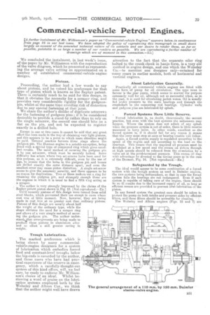
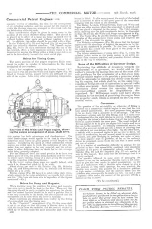
With a few exceptions, notably the London General " B " type engine (Fig. 18) and the White and Poppe engine (Fig. 10) fitted to Dennis lorries, poppet valves are arranged on one side of the engine. Like every other engineering compromise, this system has both advantages and disadvantages. The chief disadvantage would appear to be that it necessitates somewhat small valves or gives greater overall length to the engines. Considering the speed at which commercial vehicle engines are called upon to work, the restriction of valve diameter does not appear to be very material, and the advantages in other directions have no doubt led to this arrangement being generally adopted. For the camshaft drive the usual practice is to have two helical gears of steel, the pinion being hardened and the wheel, to ensure quiet running, being of a steel giving the requisite wearing properties without hardening. In the larger engines these gears are usually helical, with teeth 8 in. diametrical pitch by 1),in. wide. Silent chains ztse used in the Daimler (Fig. 19), Wolseley (Fig. 15), and Tilling-Stevens (Fig. 9); Daimler and Wolseley chains are 4. in pitch.
Belsize engines (Fig. 20) have )5s in. pitch roller chain drive, which appears to be quite satisfactory as regards both silence and life. [We have not been able to reproduce all the figures mentioned .—En . 1 Drives for Pump and Magneto.
Whea deciding upon the positions for pump and magneto, two main points should be kept to the fore. These are that the ,pump should be easily accessible for repacking the glands, and the contact breaker should be in such a position that it is not only accessible to the hands, but also so placed that the mechanism can be seen when the cover is removed.
These conditions are obtainable most readily by the fitting of a cross-shaft over the timing case.
In the " Pagefield " aerayagement (Fig. 21) this cross-shaft is set at an angle so that the pump is thrown down in line with the outlet from the radiator, and the contact breaker is lifted up to become quite the most aceessilYse part when the B52 bonnet is lifted. In this arrangement the angle of the helical gear is modified to allow of the spiral gear on the cross-shaft engaging with the wheel on the camshaft. The Halley, Leyland, Tilling-Stevens, Tylor and White and Poppe are other engines where the cross-shaft is adopted, cuid only one gland is required for the pump. The Tyler arrangement, showing also the half-compression device, is illustrated in Figs. 22 and 23, the White and Poppe arrangement in Fig. 24. The Napier (Fig. 8) and the Dorman (Fig. 25) are typical examples of the, arrangement where pump a.nd magneto are placed in line alongside the engine. The Wolseley arrangement (Fig. 26) shows that the designer appreciated the advantage of keeping the magneto as fax forward of the dashboard as possible. In this case, regard for the magneto has canned the front gland of the pump to be somewhat inaccessible.
The Albion arrangement. of pump drive (Fig. 7), where the cylinder jacket serves as the pump casing, is an entire departure from common practice, and possesses distinct advantages in the way of simplieitys
Some of the Difficulties of Governor Design.
neviewing the attitude of designers towards the employment of a governor, we would add to the author's remarks by saying that one of the most difficult problems for the originator of a first-class commercial-vehicle engine is to provide a governor which shall be adequate to restrain the driver from thrashing his engine, but which shall be at the same time, capable.of being put out of operation in special traffic or other emergency. Both these characteristics must accompany some means for ensuring that the governor-setting cannot be illegitimately disorganized. Mr. Williamson might well have drawn attention to the method of governing the engine from the propeller shaft, which is adopted on the Guy commercial motor.
Governors.
The question of the 'advisability or otherwise of fitting a governor on a commercial vehicle engine is one that has not. been settled satisfactorily. For some purposes there appears to be no doubt that a governor is of advantage. The War Department scheme calls for this fitting, and it is quite easy to understand that for night driving in convoy, without lights, it simplifies the driver's work to know that all the lorries must travel at approximately the same pace. The usual method of driving appears to be to give the engine full throttle and leave the rest to the governor. In ordinary commercial service the fitting of a governor should provide a means of ensuring that the vehicle is not over-driven When light. On the other hand, a vehicle with a governed engine is not as nice to drive, the power of accelerating beyond normal speed in ansemergency is absent, and gear changing is, perhaps, not quite to easy. The most popular type of governor, as far as the ordinary driver is concerned, seems tosbe the one that is most easily put out of action.
It is a matter of considerable difficulty to arrange for the governor to have that accessibility combined with simplicity expected of all parts of commercial vehicle engines. The Daimler (Fig. 19) and the Pagefield (Fig. 27) arc worthy of note in this respect. The latter has the advantage that it is entirely enclosed. The practice followed in some eases of arranging the governor to act on the carburetter throttle valve is not calculated to give the best results in petrol consumption. In the case of a carburetter with a throttle valve shaped to give a rich mixture at very small openings, for easy starting, the throttle may assume this position on a favourable ,gradient at, high engine revolutions, and the mixture taken into the cylinders may consequently be much too rich. In such a case a separate valve under the control of the governor affords a distinct saying in petrol.