


Patents Completed.
Page 26
If you've noticed an error in this article please click here to report it so we can fix it.
Complete specifications of the following patents will be sent to any address in the United Kingdom upon receipt of eightpence per copy at the Sale Branch, Patent Office, Holborn, W.C.
CARBURETTER.—Lewis.—No. 9,829, dated 22nd April, 1910.—The carburetter described in this specification is one in which the jet nozzle or nozzles are easily accessible without taking the carburetter to pieces. The invention is stated to be particularly applicable to carburetters having multiple-jet nozzles. The jet nozzle are arranged upon a base which is free to swing laterally, part of the wall of the jet chamber being attached to this base if necessary. In the construction illustrated this base is formed as a hollow arm which serves as a conduit to supply the fuel. The elevation and plan shoe the carburetter with a hinged member swung round through 90 degrees and allowing easy access to the nozzles. The pivot bearings are made conical and spring-supported, to ensure the joint's being kept tight and thus to prevent leakage. A further feature lies in the fact that, when the hinged member is rotated, the fuel supply is cut off, owing to the two parts of the conduit being relatively displaced, the supply end of the pipe then bedding against the solid central pivot. A spring clip is also provided to hold the two parts in operative position.
FRONT-WHEEL BRAKES.—Argylls, Ltd.—No. 6,807, dated 18th March, 1910. —This invention has reference to brakes for steering wheels of motor vehicles, and consists in an improved construction and arrangement of operating mechanism designed with a view to provide a moredirect and simplified transmission of motion to the brake shoes than hitherto. The illustration shows its application to a steering wheel in which the pivotal steering line intersects the central plane of the wheel at the point of contact of the latter with the ground. The brakeoperating mechanism is carried as far as possible on the spring-supported chassis so as to have as few unsprung parts as possible. The connection from the springborne parts to the brake mechanism con sists of a rod having a universal joint at each end and being slidably connected to one of them. The universal joint on the unsprung part of the vehicle lies in the pivotal line of steering, thus providing an arrangement whereby the operating rod is free to move with the chassis, without affecting the brakes or the steering.
TIRE—Donkin.—No. 3,112, dated 8th February, 1910.—A method of oh taming a resilient tire which is not liable ta puncture is described in this specification. A U-shaped rim is fitted to the wheel, and has stretched across the opening a band or cover which has formed on it the tread of the tire; this may be of rubber having laminations of canvas or other suitable fabric. The band is secured across the open rim by a continuous ring grasping a beading on the outside of the rim with suitable means for holding the ring in position. If desir able, the inner space contained in the rim may be occupied by an inner tube which
can be inflated. It is stated that the resiliency of ths tire is not appreciably affected by the deflation of the inner tube, but the strain on the cover is greatly increased, and the air tube serves to relieve this strain.Modifications in the arrangement are described and illustrated in the specification.
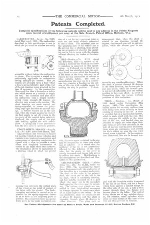
CHANGE-SPEED GEAR. — Albion Motor Co.. Ltd.—No 11,321, dated 7th May, 1910.—The accompanying figure shows diagrammatically the application of this invention to a reversing mechanism. The shaft on the right is the primary shaft, the lom er one on the left is the lay shaft, which is corstantly rotating, and has slidably mounted on it a gear wheel the upper one is the secondary shaft carrying the extra gear for reversing. The various gear wheels are controlled in their longitudinal movement by stirrups operated by cranks on a shaft set at right-angles to the others. In the case illustrated, these two cranks are set at about 60 degrees and the shaft is rotatable through about. 90 degrees in tither direction. This gives such an arrangement that, when the shaft is rotated in one direction through 90 degrees, the forward gear will be put into action, while the reverse gear is not.
moved to any considerable extent. When the shaft is rotated through 90 degrees in she other direction, the reverse gear is put into action, while the forward gear is not moved sufficiently from the neutral position to have any effect. A series of illustrations show the various working positions of this mechanism.
TIRES. — Rondeau. — No. 20,130 of 1910, dated under Convention 30th August, 1909.—This specification describes means for securing resilient tires from being torn away laterally or from rotating or creeping on the rim. A block is provided fast on a sheet-metal segment, which is made rigid with the rim; this block engages the middle of the inner side of the tire, and beaded rims are provided to engage the outer edges. Suitable wires are provided embedded in the body of the tire near the inner shoulders; these wires are continuous, and prevent the tire's riding up over the rim when lateral stress is applied. In the construction illustrated, one rim is formed inte gral with the baseplate which is secured to the rim of the wheel, and has a flange which beds against a similar flange on the other side of the rim, a bolt is then passed through these two flanges and secures them to the felloe. The central fixing blocks are of any suitable shape, as, for instance, small cylinders which enter cavities formed in the base of the tire and thus prevent its rotation.