 1
1 2
2 3
3 4
4 5
5 6
6 7
7 8
8 9
9 10
10 11
11 12
12 13
13 14
14 15
15 16
16 17
17 18
18 19
19 20
20 21
21 22
22 23
23 24
24 25
25 26
26 27
27 28
28 29
29 30
30 31
31 32
32 33
33 34
34 35
35 36
36 37
37 38
38 39
39 40
40 41
41 42
42 43
43 44
44 45
45 46
46 47
47 48
48 49
49 50
50 51
51 52
52 53
53 54
54 55
55 56
56 57
57 58
58 59
59 60
60 61
61 62
62 63
63 64
64 65
65 66
66 67
67 68
68 69
69 70
70 71
71 72
72 73
73 74
74 75
75 76
76 77
77 78
78 79
79 80
80 81
81 82
82 83
83 84
84 85
85 86
86 87
87 88
88 89
89 90
90 91
91 92
92 93
93 94
94 95
95 96
96 97
97 98
98 99
99 100
100 101
101 102
102 103
103 104
104 105
105 106
106 107
107 108
108 109
109 110
110 111
111 112
112 113
113 114
114 115
115 116
116 117
117 118
118 119
119 120
120 121
121 122
122 123
123 124
124 125
125 126
126 127
127 128
128 129
129 130
130 131
131 132
132 133
133 134
134 135
135 136
136 137
137 138
138 139
139 140
140 141
141 142
142 143
143 144
144 Torque Converter
Page 98
If you've noticed an error in this article please click here to report it so we can fix it.
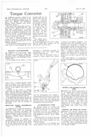
A TORQUE converter, which can be r-k made completely inoperative is the object of an improved design shown in patent No. 864,087. (M. Woodward, Margery Wood, Margery Lane, Lower Kingswood, Surrey.)
One end of the output shaft runs in a bearing inside a fixed housing (2). The other end is supported in a bearing inside the driving member, which has fixed to, it an impeller consisting of vanes (3) and a ring (4). A vaned turbine ring (5) is the driven member and revolves outside a vaned stator ring (6).
So much is common practice; the novelty in this case is that the driving member and its associated parts can be displaced endways.
In the operative position (shown in the lower half of the drawing) the usual
'toroidal path for the fluid is open and the
converter functions normally, if, however, the housing is moved to the right, as shown in the top half, the two rings (4 and 7) are separated. This completely destroys the drive, the lefthand ring acting as a cut-off valve to the fluid flow at the point (8).
The sliding movement is imparted by an annular hydraulic piston (9) to either side of which fluid pressure can be admitted by a control valve.
ROLLING VALVE-ROCKERS A DESIGN for valve-rockers which ri require no lubrication, other than oil-mist, is shown in patent No. 864,158. (Ford Motor Co., Ltd., 88 Regent Street, London, W.I.)
In the typical layout shown, 1 is the rocker and 2 a support member which may be tubular or of channel section. The action of the rocker is to roll on the Airface of the support with which it is in contact.
Location of the rockers is through guide tabs (3) which are integral with them. These fit into holes in the support, and have involute faces so that the rolling action is permitted without slackness.
The depression (4) receives the end of the push-rod and the convex surface (5) makes contact with the valve stem. An adjustment screw may be provided at this point.
REDUCING RATIO HANDBRAKE LEVER
ADESIGN for a single-pull handbrake lever which gives an increasing mechanical advantage throughout the brake application is shown in patent No. 863,512. (Neate Brake Controls, Ltd., Hanworth Trading Estate, Hanworth, Middlesex.)
Variable leverage is achieved by changing the fulcrum point of the lever. In the drawing, the lever, when pulled to the left, pivots about the pin (1) to move the pull-rod (2) to the right. The c56 movement is transmitted through an intermediate lever (3) which abuts against a fixed cam (4).
At the start of movement, there is virtually a direct simple lever action, until the intermediate lever reaches a curved portion (5) of the cam. From this position, the fulcrum point moves progressively away from the pull-rod pin and this gives an increasing mechanical advantage as the pull proceeds.
AN EMERGENCY TYRE
ANOVEL scheme for dealing with deflated tyres on the road is shown in patent No. 864,169. It is proposed to fit another tyre over the deflated one. (The General Tire and Rubber Company, 1708 Englewood Avenue, Akron, Ohio, U.S.A.) The external tyre is made in the form of a flat ring that can be placed over the defective tyre. When inflated, the tyre becomes toroidal.
In the drawing, 1 is the deflated tyre which remains on the rim; the outer tyre is shown in its inflated condition. The depression (2) is not completely circumferential, but represents a number of spaced bulges around the inner periphery. Inextensible cords (3) are located to one side of the tyre so that as inflation proceeds, a sideways rolling motion is created. The effect of this is to move the deflated tyre outwards to a position as shown at 4, so that it will not foul the vehicle.
For rapid inflation, it is proposed to provide a cartridge of compressed carbondioxide.
PETROL AND SPARKS IN SAME PIPE
PATENT No. 865,851 gives details of an unusual type of petrol injection system. The pipes carrying the petrol also function as high-tension leads, and the sparking plugs are bored through the central electrode to form nozzles. The distributor has the duty of handling both fuel and electricity. The main aim appears to be to save space in a small cylinder-head. (C. Voelcker, 52 Duckpond Road, Glen Cove, New York. U.S.A.)
KEEPING AIR FROM OIL PUMPS
PATENT No. 865,519 (Daimler-Benz A.G., Stuttgart-Unterturkheim, Germany), deals with the lubrication system of engines. When a vehicle corners, the sideways flow of oil may starve the suction side of the pump and draw in air. To prevent this, a low-level suction box is provided, with a perforated flexible bottom. This remains full during momentary changes of level.