


Simplified Steering on Multi-wheeler
Page 60
If you've noticed an error in this article please click here to report it so we can fix it.
A Resume of Recently Published Patent Specifications Obtainable from the Patent Office,Price is. each.
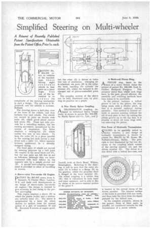
DATENT No. I 504,275 refers to. vehicles of the heaviest type, those having eight steerable wheels in four pairs on a front bogie. The aim of the invention is to reduce the Steering mechanism The patentee is W. address is Arnhem,
complexity of the in such a design. jonkhoff, and the Holland.
The drawing shows a half-plan view of the front of the vehicle, and thus includes four road wheels. The wheels are carried in pairs on double stub axles (4), which pivot about central ball joints (5). These not only provide for a swivelling motion, but the rocking movement, necessitated by the system of suspension. The latter employs a rocking-bar (3) which carries two sets of two wheels. To keep the axles (4) in a plane parallel to the rocking bar each carries a stub fitted with a roller (1), which operates between guideways in a suitably designed casing.
The front pairs of wheels are moved for steering purposes by a ball joint (6) coupled to the usual track rod (7), but the rear pairs are left free to act as followers, although they are interconnected with their fellows on the opposite side by a simple pivotal rod (2). A special inter-coupling arrangement is provided to allow of travelling in reverse.
A Sleeve-valve Two-stroke Oil Engine.
DATENT No. 503,987 comes from A.
Sampaio, .8, Chester Place, London, W.2, and deals with developments in the design of sleeve-valve two-stroke oil engines; the design. is claimed to give economy in fuel owing to the perfect scavenging.
This engine employs a sleeve (8) in which the piston works, and a stationary cylinder bead (1). The sleeve is reciprocated by a lever (4) which derives its motion from the mutual action of a pair of eccentrics (5 and 6). Eccentric 6 rotates at engine speed.
A42 but the other (5) is driven at twice this rate of revolution. Charging air is admitted, via ports (2) in the cylinder head, reaching the cylinder via recesses (3), whilst the exhaust is discharged out of piston-controlled ports (7).
The complex motion of the sleeve can be fully illustrated only by plotting its position on a graph.
A New Hardy Spicer Coupling.
A TRANSMISSION coupling, de1-1signed to withstand heavy torque loads, is shown in patent No. 504,729, by Hardy Spicer and Co., Ltd., and J.
Daniel , both of Birch Road, Witton, Birmingham. Referring to the drawing, it will be seen that the outer element (1) is bolted to a flange (5) on the gearbox, whilst the propeller shaft is flanged to the inner member (4). The actual coupling is a rubber ring (2) ; this is vulcanized to both inner and outer members, and is able to &Dr by virtue of its narrow-waisted section at the point 3.
A Multi-coil Piston Ring.
APISTON ring, made in the form of a screw thread, forms the subject of patent No. 504,608, from A.
Fischer, Budapest, Hungary. This inventor states that, whilst such rings have, in the past, proved efficient, the assembly and retaining methods have been found to he unreliable.
In the present instance a helical groove is cut in the piston, the ring being made with a shorter pitch, so that it is stressed endways during assembly. This method is claimed entirely to prevent rotation without the aid of stop pins; in fact, by cutting the piston groove up to the top face, it is possible to screw off worn rings without removing the piston.
New Form of Hydraulic Transmission.
STATED to be specially suited to I.-Imo-tor vehicles, a new design of hydraulic transmission is shown in patent No. 504,175 by W. Kruse, 26, NoIlendorfstrasse, Berlin. The principle is best illustrated by the two elements of the coupling which consist of the driving member (1) and the driven member (2). The driver is a disc fitted with a helical face-cam, and is located in the central recess of the driven member. The interior 'surface of the latter is provided with saw teeth, and these take the drive from the liquid pumped by the helical cam.
In the complete assembly, shown in the patent, three of these units, in parallel, are considered suitable for the transmission of a motor vehicle.