


Adjustable Air Suspension
Page 86
If you've noticed an error in this article please click here to report it so we can fix it.
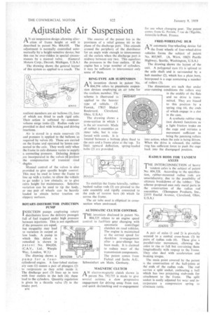
AN air suspension design allowing alteration of frame height at will is
described in patent No. 804.410. The adjustment is normally controlled automatically by a height-sensitive device, but this can be over-ridden in special circum stances by a manual valve. (General Motors Corp., Detroit, Michigan, U.S.A.) The drawing shows the general layout of this system as applied to a coach. The
resilient members are air bellows (1), four of which are fitted to each rigid axle. Their action is softened by constant volume surge tanks (2). Radius rods are provided to deal with braking and driving reactions.
Air is stored in a main reservoir (3) and pressure is applied to the bellows as required by valves (4). These are carried on the frame and operated by levers connected to the axle. They work only when the frame to axle distance varies to supply a correcting pressure. Delaying. devices are incorporated in the valves .t4 prelient the compensation of transient road shacks. Manual control of the valves is also provided to give specific height control. This may be used to lower the frame to line up with a trailer, to allow the vehicle to go tinder -a. low obstacle, or lo give extra height for maintenance. Selective variation can be used to tip the body, or one pair of wheels can be heavily loaded to obtain better traction on slippery surfaces.
ROTARY-DISTRIBUTOR INJECTION PUMP INJECTION pumps employing rotary I distributors leave the delivery passages full of fuel trapped under high pressure between injections. This is not significant If the pressures are equal, but inequality may lead to variation in output at low loads. A pump in which this defect is remedied is shown in paten t No, 804,026. (C.A.V., Ltd.. Warple Way, London, W.3.) The drawing shows a pump for •a fourcylindered engine. A fourobed stationary cam (1) causes a pair of plungers (2) to reciprocate as they orbit inside it. The discharge port (3) lines up in turn with four outlets in the belt (4); these lead to the cylinders. Quantity regulation is given by a throttle valve (5) in the intake port.
11111kimh... • El.
TaKVIwawa, 40 0,1111011 NA-Awrear tallooel "LI
u14 The essence of the patent lies in the provision of a relief groove (6) in the plane of the discharge port. This extends around the periphery of the distributor for an angle wide enough to interconnect all the outlets when the discharge port is midway between any two. This equalizes the pressures in the four outlets, If the engine has a large number of cylinders. it may be sufficient to interconnect only some of them.
RING-TYPE AIR SUSPENSION
ANinvention shown in patent No. 804,394 refers to pneumatic suspension devices employing an air tube for the resilient member. The scheme is illustrated as applied to the heavier type of vehicle. (T. Fawick, 17815 Shaker
Boulevard, Cleveland. Ohio. U.S.A.) The drawing shows a cross-section in which 1 is the air reservoir. Made of rubber it resembles an inner tube, but is reinforced with cords. It is located between a bottom plate fixed to the axle and .a frame plate at the top. To limit upward deflection, spring-loaded bolts (2) are provided.
To stabilize the frame laterally, rubberbushed radius rods (3) are pivoted to the axle assembly and rigidly connected to the ends of torsion bars (4) which lie across the frame.
The air tube used is elliptical in crosssection when unstressed.
AUTOMATIC CLUTCH CONTROL
THE invention disclosed in patent No. 804,525 relates to an engine speed control to facilitate gear changing with
automatic centrifugal clutches on road vehicles. The engine is maintained at the correct speed for shockless re-engagement after a gear-change has been made. It is claimed to reduce wear of the transmission components. The patent eomes from Fichtel and Sachs A.G., Schweinfurt am Main, Gerrnany.
MAGNETIC CLUTCH
AN electro-magnetic clutch shown in patent No. 792,755 is made to give several actions; a slow progressive engagement for driving away from rest, and quick declutching and re-engagement
for use when changing gear. The patent comes from G. Pornin, 7 rue de l'Egalite, Joinville-le-Pont, France.
FREE-WHEELING HUB .
AN automatic free-wheeling device foi the front wheels of four-wheel-drive vehicles forms the subject of patent No. 803,907. (A. Wdrn, 18821 Pacific Highway, Seattle, Washington, U.S.A.)
The drawing shows the layout of the unit. A polygonal 'cam (I) is splined to the axle shaft and is surrounded by a hub member (2), which has a plain bore, Interposed is a cage containing a number of rollers (3).
The dimensions are such that under
over-running conditions the rollers stay in the middle of the flats and no drive is transmitted. They are biased to this position by a spring ring (4), the ends of which engage in a slot in the cam.
A synthetic rubber ring
(not shown) functions as a light friction brake on the cage and initiates a movement sufficient to bring the jamming rollers into action, when the axle is being -driven. When the drive is released, the rubber ring has sufficient force to push the cage back into the disengaged position.
RADIUS RODS FOR TANDEM AXLES THE INTERCONNECTION of heavy
tandem axles is the subject of patent No. 804,328. According to the specification, rubber-mounted radius rods are unsatisfactory, due to the possibility of ultimate breakdown of the rubber; The scheme proposed uses only metal parts in the construction of the radius rod assemblies. (Thompson Products, Inc., 23555 Euclid Avenue, Cleveland, Ohio, U.S.A.)
A pair of axles (1 and 2) is pivotally secured to a central cross-beam (3) by pairs of radius rods (4). These give a parallel-ruler movement, allowing the axles to rise or fall but restraining them longitudinally with respect to the frame. They also deal with acceleration and braking torque.
The main point covered by the patent is the construction of the ball-joints at the ends of the radius rods. The rod carries a split' socket, embracing a ball which has two projecting stub-ends for attachment to the frame. The split socket is easily adjusted for wear and incorporates a compression spring to eliminate rattle,