


Double-reduction Gear in Driving Steering-head Assembly
Page 35
If you've noticed an error in this article please click here to report it so we can fix it.
VOUR-WHEEL drive is certainly in the limelight lately. Numerous inventors appear to be paying considerable attention to solving the attendant problems and evolving improved methods of applying the principle to meet practical needs.
With the desirable object of keeping the torque in the transmission line as low as possible for the greater part of the distance that it has to be conveyed from gearbox to road wheels, Scammell Lorries, Ltd., Watford, has produced a design of steering-head assembly for a front-wheel-drive vehicle, in which a big gear reduction is afforded by the mechanism actually within the unit; that is, practically at the point of application of the power.
The underlying idea, of course, is to keep down the dimensions of the shafts, gearing, bearings and so forth comprising the transmission, and there is in this Scamme11 device a double-reduction gear, virtually in the hub itself, affording a ratio of 10 to 1.
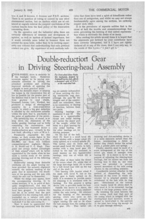
Presumably responsible for this design, as their names figure in the patent specification relating to it (No. 541,094), are those two brilliant commercial-motor engineers Messrs. 0. D. North and P. G. Hugh. They point out certain further advahtages of their scheme which will be better appreciated by the reader when he has made a careful study of the accompanying drawing and of the following description.
Noteworthy among these desirable attributes are the ample bearing surfaces provided, the accurate alignment ensured, the uniform meshing of the gears that is maintained, the sturdiness of the gearing and the ease with which the unit can be dismantled.
Whilst the design may appear, from the accompanying drawing, to be rather intricate, it is, in point of fact, quite straightforward, and may be easily understood once its main features have been grasped. To achieve this end let it be noted -that the part numbered 1 is the rotating hub, and is journalled on a tubular stub axle, whilst drive is conveyed to the unit by half-shaft 7 in the axle-casing 11.
Next it must be appreciated that the bearings associated with the steer ing are entirely independent of those carrying the driv ing mechanism an4 . that, although the axes bf the kingpin and of the counter shaft are coincident, there is no connection, or sharing of function, between these two parts.
Steering bearings are numbered 5 and 10. The former is a tapered-roller ' thrust and radial bearing and carries the major part of the weight, whilst the latter is a plain bearing for only radial loading. All the other bearings are for driving purposes.
On the end of the halfshaft (7) there is a small bevel (3) which meshes with a larger wheel (8) freely splined, on a vertical spindle (9). This carries near its lower end a second small bevel (4) which, in turn, meshes with a ring bevel gear (3) bolted to the hub (1) mounted in usual manner on two tapered-roller bearings, only one of which (2) is shown.
The other of these takes the thrust 'of the crown wheel (3), whilst that of the large first-stage bevel (8) is taken by a ball thrust race (12) on the top end of the shaft 9.
This bearing (12) locates wheel 8 for mesh with bevel 6, but as the larger gear is freely splined on its shaft, it is necessary to provide means for retaining it in abutment with its backing. For this purpose a spring device (13) is provided under its boss.
Outside this device is a sleeve, the function of which is to retain lubricant within the axle casing. Oil retainers for the housing of the secondary gearing, which also serve as dirt excluders, are provided around, the spigot bearing (5) and at 14 where the hub emerges from the casing of the ring gear (3). This latter oil
retaining and dirt-excluding device is of a more elaborate nature than the former, incorporating a fabric or leather ring (which makes the actual joint), a presser plate and springs.
Finally, mention must be made of a screw arrangement at the top of the swivel pin where it emerges from bearing 10. It is stated to be for the purpose of adjusting the steering-head bearings, but we cannot see from the drawing how it does so, nor what means are provided to prevent upward movement of the axle casing relative to the swivelling assembly.
Considerable interest attaches to the method of dismantling the unit. Removal of the cover to which oilretainer 14 is attached permits the withdrawal of the hub with its ring gear. Detachment of the bottom cover (under bevel 4) allows shaft 9, with bevel 4, to be extracted, leaving behind it the large primary bevel (8).
By breaking the joint between the axle casing itself and that part of the casing which is integral with the steering-head fixed members, access is gained to bevel-wheel 8, the aperture at the joint face being big enough for it to pass through sideways.