


Features in Petrol Tank-wagon Design.
Page 7
If you've noticed an error in this article please click here to report it so we can fix it.
The fact that the Editor of this journal was called upon to give evidence before the Home Office Committee on Petroleum has been duly recorded in our pages. At the request of that committee, he recently submitted a proposed outline specification for a 1200gallon tank, to meet the purposes in view, and we now have pleasure in stating, for the information of our readers, some of the points that have been so put forward.
No Need for New Speed Limits.
We fail to see that there is any occasion for the imposition of new speed limits upon drivers of motor tank-wagons, when these vehicles are loaded with petroleum spirit. The existing provisions of the Heavy Motor Car Order of 1904, with regard to axleweight in relation to speed, will automatically limit the maximum permissible speed of a 1200-gallon tankwagon to 8 m.p.h., seeing that the back-axle weight must, in all circumstances, exceed six tons when the vehicle is laden, and will similarly limit the speed of a 900-gallon tank-wagon to 12 m.p.h. We consider that these maximum speeds will he perfectly safe, provided the section of the tank is not less than in. thick in the body, with the ends / in. thick. It is suggested that the tank should be welded at all permanent joints, and proved petroleum-tight, or tested by internal hydraulic pressure, to 50 lb. per sq. in.
Points about Tank Design.
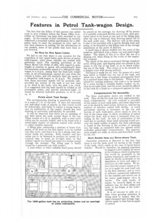
The accompanying drawing is practically accurate to a scale of 1 in. to the foot. It does not represent any individual make of chassis, as that course would be undesirable, and liable to convey a wrong impression on publication of the report, should any such drawing of particular individuality be included. It will be observed that there are no openings of any kind about the tank, except those in the top. These consist of a 16 in. manhole, with a steel cover which can be securely bolted, and to be fitted with a petrol-tight. washer of asbestos coated with shellac or other suitable material.
A filling pipe, containing a strainer of brass wiregauze, of 50 mesh to the inch lineal, is to be welded into this cover, and there is to be a strong steel protector inside the strainer. Both strainer and protector are to be fastened in position by means of a screwed ring, to make an air-tight joint, so that neither vapour nor liquid can enter nor escape except through the strainer. The filling pipe is finally closed by a gunmetal cap with washer.
A semi-rotary or other suitable hand pump should be placed on the carriage, for drawing off by means of a suitable armoured flexible petrol hose, with gunmetal union to be .fixed on the end of the filling pipe after the cap is removed, thus drawing petrol out of the tank under seal. The delivery side of the pump is also to be provided with a similar flexible hose and union, to be attached to the filling inlet of the storage installation at the point of delivery. A small pipe is shown welded into the cover of the manhole, and fitted with a brass cap and petrol-tight washer. The object of this is to allow the use of a dipping rod, when filling at the works of the supplying company. The whole of the above-mentioned fittings (manhole cover, filling pipe, and dipping pipe) are placed in the recess in the top of the tank, so as to stand within the top of the tank. This recess is to be secured by a hinged cover with strong padlock. Provision is made for air vent, by means of a steel boss which is welded into the top of the tank, and which has a. fine brass wire-gauze permanently fixed by a screwed brass ring in the bottom. When not required for venting purposes, this vent is to be closed by a screw having a suitable leather washer, to ensure an air-tight joint, and the screw should be affixed to the tank by a chain as a safeguard against its loss.
Compartmented, Yet Accessible..
The three wash-plates shown are welded to the shell. They divide the tank into four approximatelyequal compartments. An oval manhole is provided at the centre of each wash-plate, and these man-holes are to be closed by steel covers, bolted on, and having washers of asbestos coated with shellac. A small permanent opening is necessary in the top and bottom of each wash-plate, about equal in area to that of the pump pipe, to allow circulation of petrol within the tank, and to keep it balanced when travelling on the road. In case of perforation of the shell due to accident, these small openings would prevent the rapid outflow of petrol, but their advantage is found in the limiting of the number of openings into the tank, as compared with any scheme which embodies petrol-tight compartments. The approximate weight of a tank, as shown and described, would be 22?,4 cwt.
Much Stouter than any Horse-drawn Tank.
Particular attention is directed to the fact that there is not the same need, for saving in the weight of the tank, which exists in the case. of horse-drawn vehicles. Should it, therefore, be deemed expedient to suggest a shell slightly in excess of the thickness which is proposed, this would be acceptable to the parties concerned, and would certainly be wholly preferable to the imposition of route and other restrictions of a like nature. We believe that the proper course to follow is to make the tank itself safe in the first instance, and to trust to ordinary commercial influences for the sensible and careful use of the motor tank-wagons when in service. The tank would, of course, be securely fixed, in any ordinary way, by steel straps arid bolts, to the frame of the undercarriage.
It is of interest to add, at a time when growing attention is being paid to benzol. that the same transport and storage regulations apply to that fuel as apply to petrol.