


MECHA
Page 66
If you've noticed an error in this article please click here to report it so we can fix it.
Lighting systems
E WIRING SYSTEMS used motor vehicles are of two ds; on private motor cars and ht commercial vehicles the arth return" system is iployed, while on the heavier hides an insulated return 'out is favoured.
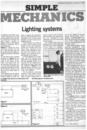
Figure 1 shows an insued return system for one np. It will be seen that the th to and from the battery to ;bulb is provided by insulated ales.
In the earth return system J st ra t ed in Figure 2 one .minal of the battery is concted to the frame of the hide. The cable from the ler terminal carries the curit to the bulb, and after pasig through the filament of the lb the current returns to the ttery via the metal frame of ?, vehicle.
This method has the advan)e of reducing the number of Jividual cables by half, but there is always the possibility that at a point where the return connection from a lamp meets the body, corrosion may cause a defective circuit.
If the insulation on a cable of an earth return system gets chafed so that the conductor comes into contact with the frame then, because of the heavy current allowed to flow, the wire will become overheated, the insulation burnt, and possibly a fire caused.
A wiring diagram for a head, side, tail and number-plate lights with a rear foglight wired into the sidelight circuit, as is required by the Regulations, and using the earth return system, appears in Figure 3. The lighting switch has three positions, in the diagram it is shown in the "off' position.
If it is turned in a clockwise direction it first makes contact with the sidelamp terminal. When turned a little further it
makes contact with the headlamp, terminal, but because of the "tail— attached to it the sidelamps are still connected into the supply.
The current flows from the lighting switch to the dipswitch and here the current is directed to the "main" or "dipped'' circuits depending on the posi
tion of the "blade— in the dipswitch. When in the "main" position, a warning light to inform the driver that the system is on "main" beam is brought into use, being connected into the main circuit.
Bulbs used on motor vehicle lighting equipment have helically wound tungsten filaments and the bulbs are filled under slight pressure with an inert gas such as argon. Some bulbs have two filaments, for example twin-filament bulbs are often used to provide rear and stoplights in one lamp. Similarly, main and dipped beams on headlamps are invariably provided by twin filaments.
Many headlamps are now fitted with sealed-beam units instead of ordinary bulbs. These consist of a special glass unit housing the filaments. An aluminised reflector is permanently joined to the lens, and as the unit is always sealed it is not possible for dirt and moisture to damage the reflector.
The filaments are precisely located in the reflector during manufacture, and there is no possibility of them becoming misplaced. Sealed beam lamps suffer from the disadvantage that when a filament fails the whole unit has to be replaced instead of just having a new bulb fitted.
The photo shows a typical front lamp layout for a modern heavy vehicle.
It is always desirable to have a fuse in electrical circuits so that in the event of a shortcircuit, the fuse "blows" instead of damage being caused to the wiring.
In lighting circuits it is safer if a separate fuse is used for each lamp so that if a fuse melts only one lamp is extinguished instead of there being a complete "blackout," as would be the case if one fuse protected the entire lighting system.