


HINTS ON MAINTENANCE.
Page 56
If you've noticed an error in this article please click here to report it so we can fix it.
How to Get the Best out of a Vehicle, to Secure Reliability and to Avoid Trouble.
673.—Measuring the Valve Travel on the Foden.
Most Of the engineers in charge of Foden steam wagons are quite capable of settiag the slide valves of the engine, but few are acquainted with the importance of having the valve travel correct, and the result of neglect of this matter is loss of power and waste of fuel and water, causing dissatisfaction both to the driver and to the owner of the vehicle.
The valve travel of any slide-valve engine is as important to a steam vehicle as the magneto timktg is to a petrol engine.
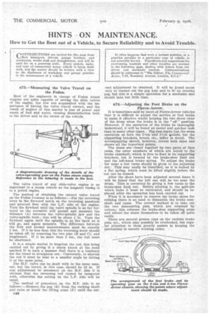
The method of obtaining the correct valve travel on the Foden 5-tortner is as follows :—Put the reversing lever in the forward notch on the reversing quadrant and "proceed first with the L.P. side of the engine. Turn the flywheel until the valve spindle is as far for-ward as the eccentric will permit and measure the distance (A) between the valve-spindle jaw and the valve-spindle bush; this will be about in. Turn the flywheel again until the spindle is as far back as it will go, and again measure. The difference between the first and second measurements must be exactly 2 ins. If it be less than this the reversing lever should be taken off, by removing the two pins (B and C), and lengthened. If it be more than 2 ins., the rod must be shortened.
It is a simple matter to lengthen the rod, this being carried out by giving it a sharp knock at the _bend marked D in such a manner that there is a tendency for the tread to straighten out.Conversely, to shorten the rod it must be bent to a smaller angle by hitting it at the same point.
The H.P. valve can be dealt with in the same manner, but the travel, in this case, should be 11 in. If any adjustment be necessary on the H.P. side it is obvious that the reversing rod cannot be tampered with, otherwise the setting on the L.P. side will be upset.
The method of procedure on the H.P. side is as follows :—Remove the peg (E) from the rocking shaft and raise or lower the lifting arms (F) until the eor c40
rect adjustment be obtained. It will be found necessary to reamer out the peg hole and to fit an oversize peg, but this is a simple operation for a mechanic and should take but little time.
674.—Adjusting the Foot Brake on the Pierce-Arrow.
It is-sometimes said by users of Pierce-Arrow vehicles that it is difficult to adjust the service or foot brake to make it effective whilst keeping the two shoes clear of the drum when the brake is in the " off " position. However, if the operation of the brake be thoroughly understood, it -will be found an easier and quicker task than in many-other types. The foot-broke has the same operation on both the 2-ton and 5-ton vo-dels, but the supporting brackets, levers, etc., differ in detail. The aceompanying sketch, however, covers both sizes and shows all the important points.
The shoes a're .closed together by two pairs of face cams, the outer members of which are keyed to the brake camshaft,.which is free to float in its supporting brackets, but is located by the brake-shoe limit nut and the left-hand brake spring. To adjust the brake for wear a few turns should be given to the adjusting nut: This may easily be identified, as it is locked by a flat spring, which must be lifted slightly before the nut can be turned.
After the shoes have been adjusted several times it will be found that the left one will be too near the drum. This is corrected by giving a few turns to the brake-shoe limiet nut. Before altering it, the split-pin which locks it must be extricated, and should be replaced after the operation has been carried out.
When it is necessary to remove the brake shoes for relining there is no need to dismantle the brake camshaft and cams. The correct method is to take out the two demounting pins, which are retained by cotters; this releases the brake-shoe supporting arms and allows the shoes themselves to be taken off quite easily. There are several grease cups on the various brake pins, etc., which may possibly be overlooked, but reguJar attention to them greatly assists in keeping the mechanism in smooth working order.