


Patents Completed.
Page 22
If you've noticed an error in this article please click here to report it so we can fix it.
Complete specifications of the following patents will be sent to any address in the United Kingdom upon receipt of eightpence per copy at the Sale Branch, Patent Office, Holborn, W.C.
ROUTE INDICATOR.—Woodyer.— No 10,333, dated 2'7th April, 1910.—In this specification is described an indicator for showing omnibus and tramway
routes "in such a manner that strangers not familiar with the town or neighbourhood can easily recognize the car which they must take to arrive at a desired destination." The indicator consists essentially of a map of the lines or routes in the neighbourhood, combined with a suitable revolving screen mounted on rollers; upon this screen are provided the names of the different routes, and any other desired particulars, such as the principal streets and roads which the car will pass, the time taken for the journey, the frequency of the car service, and so forth. In an alternative construction, the information is displayed on a large disc which can be rotated to show the special feature required. Another advantage of the construction is that it lends itself very conveniently to illumination by transmitted light by the use of transparency screens; advertisement spaces may also be provided surrounding the screen.
DRIVING PUMPS.—Marryweather. —No. 27,143, dated 22nd November, 19111—This invention refers to automobiles carrying pumps, particularly the
type of pump described and illustrated in Specification No. 529 of 1908. The feature of the present invention lies in driving the pump by a chain drive instead of by a spur wheel and pinion. In the original construction, the pump rotates in the direction opposite to that of the engine, and this causes vibration to be set up in the framework of the carriage which it is difficult to counteract. By means of the chain drive, both pump and engine run in the same direction, and the balancing of the moving parts is facilitated.
INTERNAL COMBUSTION ENGINE.—Flamilton.—No. 5,873, dated 9th March, 1910,—This invention relates to two-stroke engines of the type having a piston of two diameters, of which the smaller or upper one forms the working piston, and the larger forms an annular pump for compressing the mixture. According to this construction two cylinders are mounted adjacent to one another, and they have situated between them a rotary valve. This valve has ports communicating with the annular pumping chambers and with the working
portions of the two cylinders, and it. is also arranged to place the carburetter in communication with the pumping chambers. One end of the valve which is hollow is connected with the induction pipe from the carburetter, and has ports formed in it communicating with passages to the pumping chamber, the other end of the valve is formed with a crossways port which, as the valve is rotated, places the pumping chamber of one cylinder in communication with the working part of the other cylinder, The valve Is driven by any suitable gearing from the crankshaft at the requisite speed. The mixture is drawn into the pumping chamber, compressed and passed into the other working cylinder, thus assisting in the removal of the exhaust. It is again compressed and ignited when the piston reaches the top of its stroke, and the cycle is repeated.
A METHOD OF HEATING ROAD MOTOR VEHICLES. — Leaver. — No. 303, dated 5th January, 1910.—This invention provides for the heating of vehicles, such as motorbuses, by means of waste heat from the internal-combustion engine. A hot-water circulating system is arranged within the vehicle in any convenient position where the heat can be usefully distributed; this system is connected with the water-circulating sys
tem for cooling the engine. The heating of the vehicle is controlled by throttling the flow of water ; this control may be manual or automatic by means of a suit able thermostat operated by the internal temperature of the vehicle. These radiators are arranged in parallel with the ordinary radiator on the engine, and the water is diverted into them when necessary.
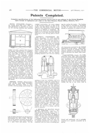
CARBURETTER.—Lewis.—No. 9,708, dated 21st April, 1910.—This carburetter is of the type provided with multiple jets, and, according to the invention, the choke tube for one jet forms a. valve for cutting off the other jet or jets. The illustration shows the construction as applied to a two-jet carburetter. The first or smallest jet is arranged concentrically and around it is located the choke tube which stands in a passage of larger diamiter ; on the choke tube is formed a flange, which seats on the top of the vertical passage and normally cuts off the passage from the carburetting chamber except by way of the interior of the choke tube. The second jet nozzle is located eccentrically in the vertical passage, and consequently no air can pass by its nozzle unless the choke tube and its flange are raised. It is stated that preferably the top of the choke tube is
domed and perforated, and is suitably mounted on a spindle controlled by a spring.