


Rocking-floor Low-loading Trailer
Page 32
If you've noticed an error in this article please click here to report it so we can fix it.
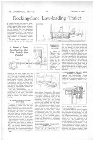
CABLE-DRUMS and electric transformers are typical of the loads for which a special trailer, shown in patent No. 513,598 is designed. The patentees are G. Griffith and the Armstrong Manufacturing Co., Ltd., 52, Bunhill Row, London, E.C.1. The object is to provide a short trailer that can tilt to the ground without at the same time forming an excessive loading angle.
The main frame members (1) are mounted high up on the body, and extendd, to the front whore they are triangulated to meet at the towing eye (2). The axle is sprung from these members, and is downswept where it passes under the body. The floor of the vehicle is a separate member, and is pivoted on pins (4) so that it can, when loading, be tilted into the position shown, the tilting motion being imparted by an hydraulic cylinder (3) operated by a hand-pump.
The rear floor-extension (5) is normally carried in a vertical position at the back of the load. The usual hauling winch is provided, also screwjacks to steady the vehicle during loading.
A TORQUE INDICATOR FOR SPANNERS I T requires a considerable amount of judgment to tighten down the nuts of a cylinder bead to exactly the right degree, and even good mechanics occasionally have the annoying experience of twisting off a stud. To prevent this is the object of a device shown in patent No. 510,363, by Precision Wireless Devices, Ltd., and J. Naden, both • of 51a, Claxton Grove, London, W.6.
The apparatus consists of an inner rod formed into a spanner at its lower end, and an outer sleeve to which is applied an ordinary spanner or tommy bar. The relative torsional displacement between the two members is shown on a dial, and this indicates to the user the exact force being applied.
1130 Road, Hilsea, Portsmouth. The object is to enable any vehicle to be hastily converted for A.R.P. or similar duties.
The main supporting frame (2) for the trailer eye is attached to the most convenient point on the towing vehicle without regard to strength. As shown in the drawing, this will generally be the floorboards (1). To withstand the actual towing pull, a chain (4) is hooked around a chassis crossmember, and is then tightened by a strainer bolt (3) until taut. Overrunning stresses are taken by a pair of compression struts (5) whilst any tendency to lift is resisted by a screwclamp (6) on the rearmost batten. Another design shows an additional feature—an up-and-down adjustment for the towing eye to avoid excessive drawbar angles.
DISTORTION-FREE FOUR-POINT MOUNTING
PATENT No. 513,667, from Coinmer Cars, Ltd., W. Limon and A. J. Swift, all of Luton, deals with this con
cern's method of mounting the forward part of the body, that is, the driver's cab, the scuttle, the front wings and the radiator. The object is to prevent distortion of these parts caused by travelling over irregular ground.
The parts mentioned above are all mounted on a separate light sub-frame, and this is attached to the main frame via four pivot points, two lengthwise and two crosswise to the frame, as shown in the drawing. 13y this means angular distortion between any pair of parallel members of the main frame is not imparted to the sub-frame. The scheme is also said to be equally applicable to the suspension of the whole of the body.
FLUID-OPERATED BRAKE WITH MOVING CYLINDER
ONLY one pressure-tight sliding ‘.../joint is needed in a design of compressed-air or hydraulic brake shown in patent No. 513,666 by Bendix, Ltd.,
and G. Roberts, both of King's Road, Tyseley, Birmingham.
The scheme refers to brakes in which the shoes are separated by a sliding wedge moving at right-angles, and the drawing shows a section of the wedge and operating mechanism. The piston (3) in this case, is stationary, being carried by a rod (4) anchored by a cross-pin (5). The cylinder (1) is the moving member, sliding as a whole to .
or from the rest of the brake. The motion is transmitted to the wedge via a sleeve portion (6) which is slotted to clear the cross-pin. For mechanical operation, the cylinder carries a yoke (2) for the attachment of the rodwork.