


Ball-weight-operated Centrifugal Clutch
Page 62
If you've noticed an error in this article please click here to report it so we can fix it.
improved design of automatic clutch is shown in patent No. 494,368, which comes from G. Hayter and the Northern General Transport Co., Ltd., 88, Kingsway, London, 1.V.C.2. The clutch is centrifugally controlled, and is of simple construction, employing only a number of balls in addition to the normal components.
In this case, the clutch plates are lightly loaded in a separating direction by a number of springs (2). • The outer cover contains 16 to 24 sloping bores (1) each of which contains a ball. At speed., the balls are urged outwardly, and exert a pressure on the clutch plates. Another design shows a similar construction with the addition of manual control.
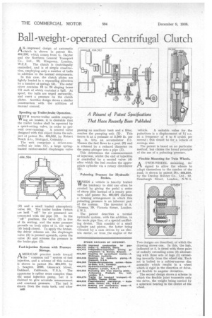
Speeding up Trailer-brake Operation.
WITH tractor-trailer outfits employW ing air brakes, it is desirable that the trailer brakes shall be operated by a quick-acting valve, in order to pre
vent over-running. A control valve designed with this object forms the subject of patent No. 494,584, by Robert Bosch A.G., Stuttgart. Germany.
The unit comprises a driver-controlled air inlet (1), a large springloaded rubber-seated diaphragm valve (2) and a small loaded atmospheric valve (4). The trailer brakes (which are held " off" by air pressure) are connected with the pipe (3) . In the off" position, the valve (2) is free of its seating, and the same pressure prevails on both sides of it, the valve (4) beint closed. To apply the brakes, the driver releases air, the diaphragm valve (2) is pressed upwards, opens the valve (4) and releases the pressure in the brake-pipe (3).
Fuel-injection System with Pressure . Storage.
AMERICAN practice tends toward the "common rail" system of fuel injection, and a scheme of this nature is shown in patent No. 494,580, by J. Seagren, 2896, Glasscock Street, Oakland, California, U.S.A. The apparatus is rather more complex than the usual injection pump, but it is claimed to give accurate measurement
and constant pressure. The • fuel is drawn from the main tank, add alter B48 passing an auxiliary tank and a filter, reaches the pumping unit (2). This forces it at a pressure of 3,500 lb per sq. in. into an accumulator (1). Thence the fuel flows to dport (6) and is released by a reduced diameter on the pump plunger into a pipe (3).
This determines the commencement of injection, whilst the end of injection is controlled by a secdnd valve (4) after which the fuel reaches the appropriate cylinder via a rotary distributor (5).
Pulsating Pressure for Hydraulic Brakes.
WHEN a vehicle is heavily braked W the tendency to skid can often be averted by giving the pedal a series of sharp jabs instead of a steady pressure, and patent No. 493,697 discloses a braking arrangement in which this pulsating pressure is an inherent part of the system. The inventor is A. Thomas, 39, Victoria Street, London, S W.1.
The patent describes a normal hydraulic system, with the addition, in the main pipe line, of a special oscillating device. This consists of a small cylinder and piston, the latter being vibrated by a cam driven by an electric motor, or from the engine of the vehicle. A suitab e value for the pulsations is a displacement of 1i c.c. at a frequency of 4 to 6 cycles per second ; this would be for a vehicle of average size.
The patent is based on no particular method, but claims the broad principle of the use of a pulsating pressure.
Flexible Mounting for Twin Wheels.
PA.A TWIN-WHEEL mounting, designed to allow the wheels to adapt themselves to the camber of the road, is shown in patent No. 493,894, by the Dunlop Rubber Co., Ltd., 32, Osnaburgh Street, London. NAV .1.
Two designs are described, of which the drawing shows one. In this, the hub, indicated at 2, is fitted with three pairs of radially extending arms (3) alternating with three sets of lugs (1) extending inwardly from the wheel rim. Each set is bolted to a rubber-canvas disc assembly which results in a wheel which is rigid in the direction of drive, yet flexible to angular deviation.
The second design shows a scheme in which the flexible joint transmits only the drive, the weight being carried by a spherical bearing in the centre of the wheel.