


ECONOMIZING FUEL BY ATOMIZATION.
Page 30
If you've noticed an error in this article please click here to report it so we can fix it.
A Résumé of Recent Patent Specifications,
Tut' main object of patent specification No. 223,958, granted to Sir A. Trevor Dawson, Bart., R.N., and Sir G. T. Buckham, both of Vickers, Ltd., Westminster, appears to be the provision of a means whereby the vehicle can be steered quickly and with ease in a very short circle, and without undue effort on the part of the driver.
As will be seen from the upper illustration, • the general lines of the front resemble the Ackerman steering, but each group of wheels is mounted on a separate bogie. The connecting rods are crossed and are connected to a quadrant plate. The rear wheels are mounted on the bogie, which pivots on a pin, and both move together for the purpose of steering, as shown in dotted lines.
The bogie of the rear wheels and the quadrant plate are both provided with segmental worm racks.
Both these racks engage the worm, and it will be seen that if this worm be revolved it. will impart a steering movement to both front and back wheels, as
shown in dotted lines. It is obvious that, to effect steering in this manner, considerable power would be required, snore, in fact, than could be expected by the turning of a wheel by the driver in the ordinary way:' It will be seen that a shaft (f) is provided with a gearwheel, which engages a similar wheel on the worm shaft. The shaft (f) is connected to the 'engine, and is always revolving. In the lower illustration details of the shaft (1) will be seen, and it will be noticed that the gearwheel referred to is mounted on a sleeve and is, copses fluently, free to remain still while the shaft (f) may continue to revolve. The shaft (f) has a bevel wheel attached to its outer end, whilst a casing provides support for two bevel pinions, and a second bevel wheel is provided, this is attached to the sleeve above referred to, which carries the gearwheel which engages that on the worm shaft. So far this part resembles an ordinary differential gear. Its outer casing is surrounded by a brake band, whilst a multi-plate friction clutch is provided, so that friction can be set up between the outer casing and the bevel wheel on the end of the shaft (f). It will be seen that by Applying either the brake band or the friction clutch rotary motion can be set up in the worm shaft (f) in either direction in which it may be required. The' brake band and the friction clutch are both controlled by the quadrant shown, which is actuated by a worm attached to an ordinary steering post, as shown in the right-hand lower illustration.
No details are shown of the proposed means of teansinitting power to the back wheels front the engine, but this is effected by means of a hollow kingpin (b).
to be used for a given power developed. They claim that, in seine cases, the economy effected by the use of their invention has brought about a saving of fuel that in some eases has amounted to 50 per cent. The main principle calls for two passages opposed to each other, through which the mixture is drawn, so that the two streams impinge directly upon each other, and so bring about a more intimate mixture than would otherwise be possible.
Apart from the saving in fuel, the inventors claim that the gas is excited by impact into a more sensitive condition, and that it explodes more readily. This they, attribute to electric activity of the molecules brought about by impact.
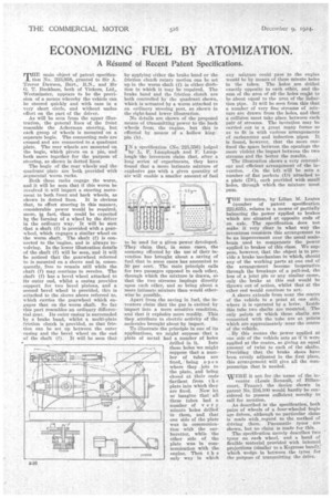
To illustrate the principle in one of its applications, we might suppose that a plate of metal had a number of holes drilled in it. Into these holes we might suppose that a number of tubes are fixed, being open where they join to the plate, and being closed at their end 'farthest from t h e plate into which they are fixed. Now let us imagine that all these tubes had a number of v er y minute holes drilled in them, and that one side of the plate was in communication with the carburetter, while the other side of the plate was in communication with the engine. Then t h e only way in which any mixture could pass to the engine would be by means of these minute holes in the tubes. The holes are drilled exactly opposite to each other, and the sum of the area of all the holes ought to be about equal to the area of the induction pipe. It will be seen from this that a number of very fine streams of mixture are drawn from the holes, and that a collision must take place, between each pair of streams. The invention may be carried out in a great many forms so as to fit in with various arrangements of carburetter and induction pipes. It is found, however, that the more confined the space between the openings the more violent the impact between the two streams and the better the results.
The illustration shows a very conveuient and efficient arrangement of the in vention. On the left will be seen a number of flat pockets (D) attached to a plate (Di), each prodded with small holes, through which the mixture must pass.
THE invention, by Lilian M. Leates
(number of patent specification 223,635), relates to a means of partially balancing the power applied to brakes which are situated at opposite ends of an axle. The .specification does not make it very clear in what way the inventress considers this arrangement to be an improvement over the usual scalebeam used to compensate the power applied to brakes of this class. We suppose, however, that the object is to provide a brake Mechanism in which, should any of the working parts at one end of the arrangement become inoperative through the breakage of a pull-rod, the loss of a joint pin or any similar cause, only the brake at this end would he thrown out of action, whilst that at the other end would continue to act.
A sleeve extends from near the centre of the vehicle to a point at one side, where it is operated by lever. Inside this tube two shafts are mounted. The only points at which these shafts are connected with the tube are at points which are approximately near the centre of the vehicle.
. By this means the power applied at one side of the vehicle acts as if it were applied at the centre, so giving an equal amount of twist to each of the shafts. Providing that the brake shoes have been evenly adjusted in the first place, this arrangement will give all the compensation that is needed.
WERE it not for the name of the in ventor (Louis Renault, of Billancourt, France) the device shown in patent No. 216,100 would hardly be considered to possess sufficient novelty to call for mention.
As described in the specification, both pairs of wheels of a four-wheeled bogie are driven, although no particular claim is made with ,regard to the method of driving them. Pneumatic tyres are shown, but no claim is made for this. The specification merely describes two tyres on each wheel, and a band of flexible material provided with internal projections (similar to a Kegresse band); which wedge in between the tyres for the purpose of transmitting the drive.