


A SIMPLE MECHANICAL TIPPING GEAR.
Page 20
Page 21
If you've noticed an error in this article please click here to report it so we can fix it.
Modern Tendencies. Details of the Latest F.W. Gear made by F. Walters and Co., and of a Simple but Efficient Universal joint of a New Pattern.
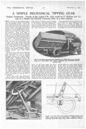
eillErE evolution of the modern tipping _L geae is a matter which can be studied with eonsidereble interest. From the simple hand-operated screw gears which were fitted some years ago developments reached such a stage that many gears became of far too complicated a nature, requiring a considerable amount of attention if they were to be kept to their full efficiency. Many were liable to seizure and consequent damage through being open and vulnerable to the effects of sand, stone and other material carried in the bodies and apt to fall right on to the gears. Consequently, the modern 'trend is all towards simplicity, even where the gears are power driven, and of these one of the neatest and most smooth acting which we have examined is the F.W., patented and manufactured by F. Walters and Co., of Rugby, the makers of the well-known Pioneer sweeping and loading machine, Simplex gritting machine and other useful devices.
The F.W. gear, which can be employed with equal facility for end or side tipping, providing the gear is suitably arranged, consists of a short, squarethreaded screw forming a sleeve within which works a secondary screw. To eliminate friction between them there is an intermediate phosphor-bronze sleeve, screwed internally and carried in the upper portion of the large screw. The last named is carried in a spherically surfaced support, technically known as the footstep, and the footstep is mounted in, and driven by, a spherical housing, the upper half of which is formed in one with a phosphor-bronze worm wheel. whilst the lower half is of hardened steel and extended to form the cone of a ball race.
In the early models the driving connection between the spherical housing and the footstep consisted of larga steel balls carried in suitably curved grooves in the housing and semi-circular holes in the footstep, thus also providing a neat and smooth-acting universal joint which permitted the screws to work in any angle necessary for tipping per poses. In the latest design the drive has been still further improved by the use of special driving keys, as they may be termed, each being formed as half a ball and the other half as a segment of a ring, the surface of which has as a radius the distance between the centre of the footstep and the curved grooves in the housing, By the use of these keys instead of balls the area of contact between the keys and the grooves in the housing has been considerably increased. The worm wheel and its driving worm are carried in a stout casing, into the lower part of which is fitted the hardened steel cup; between which and the cone on the lower half of the spherical housing are inserted steel balls form ing the thrust race upon which the load of the body is carried while tipping. This race is of large diameter and, consequently, there is little overhang of the worm wheel teeth and no tendency for the worm wheel to tilt under load.
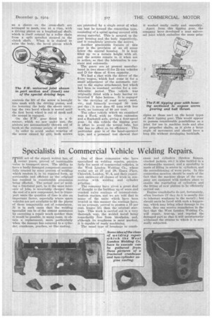
The usual practice in arranging the drive is to provide a cross-shaft for the. worm, and when the gear is handoperated the handle is attached direct to this cross-shaft ; but, where arranged for power operation, two bevel pinions on a sleeve on the cross-shaft are arranged to mesh, one at a time, with a driving pinion on a longitudinal shaft, which is itself rotated by a roller chain from a split sprocket secured rto the clutch shaft. When it is desired to raise the body, the bevel pinion which controls the lift of the screw is brought into mesh with the driving pinion, and for lowering the body the sleeve carrying the two bevel wheels is moved until the first bevel wheel is out of mesh and the second is engaged.
On the F.W. gear fitted to a 6tonnes, which we saw under test, the pinions are automatically thrown out of mesh at the extreme points of control.
In order to avoid undue wearing of the screw caused by grit, both screws are protected by a single cover of what can best be termed the concertina type, consisting of a spiral spring covered with strong material. This is secured to the gear housing and the body respectively, and it completely protects the screws.
Another practicable feature of this gear is the provision of an oil sump below the central housing, It is kept filled up to a certain height with oil, and the screws remain in it when not in action, NO that the lubrication is constant and automatic.
The gears are at present manufactured in two sizes—I3 for 24-ton vehicles and D for those of 6-ton capacity.
We had a chat with the driver of the 6-ton wagon, which had come in for a small adjustment of -the automatic cutout to the engine attachment, but which had been in constant service for a considerable period. This vehicle was originally fitted with a body having an inverted V false bottom. It is engaged in the carrying of wad metal, sand, etc., and formerly averaged 30 tons per flay; it now does 42 tons with less work, an increase of 40 per cent.
The other vehicle which we examined was a Ford, with an Olson extension and a Ruckstell axle, giving a four-speed gear. In this vehicle the tipping gear is offset to avoid the torque tube, but this has no effect on its efficiency. • This Particular gear is of the hand-operated type, and a personal test showed that
it worked really easily and smoothly. Apart from this tipping gear, the company have developed a neat universal joint which embodies the same priu eiples as those used on the latest types of their tipping gear. This would appear to possess considerable possibilities as a joint for use in machine tools and also for propeller shafts, as it givs a large angle of movement and should have a long fife without developing backlash.