


THE BOVIER-DELVILLE ENGINE.
Page 12
Page 13
If you've noticed an error in this article please click here to report it so we can fix it.
An Engine Embodying Several Novel Features Including Steel-lined Aluminium Cylinders.
efiElE success of a new engine depends I chiefly upon two main factors— those factors are experience on the part of the manufacturers and quality of the materials used. R Bolder and Co., Ltd., Kingsgate Place, Quex Road, Kilburn, have recently designed an engine which embodies several novel and practical features. During the war this company was almost exclusively engaged in the) manufacture of aeroplane engines, of which they turned out several thousand. The experience gained in this direction has been turned to use in the design of their latest production, and all the materials used in its construction are to Air Board specifications, which are very severe, as, naturally, only the very best materials can be used in engines required to undergo such severe tests as are necessary in aerial work.
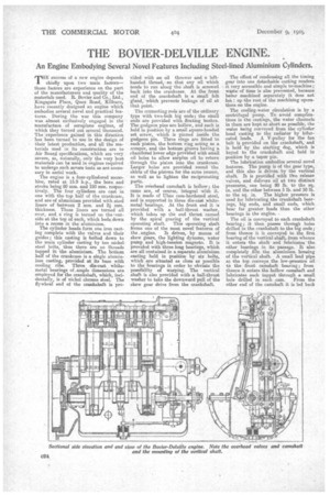
The engine is a four-cylindered Homobloc, rated at 15.9 h.p., the bore and stroke being 80 mm. and 150 rem. respectively. The four cylinders are cast in one with the top half of the crankcase, and are of aluminium provided with steel liners of between 2 mm. and 2 mm. thickness. These liners are turned all over, and a ring is turned an the 'outside at the top of each, which beds down into a recess in the aluminium.
The cylinder heads farm one iron casting complete with the valves and their guides; this casting is bolted down to the mein cylinder casting by ten nickel steel bolts, thus there are no threads tapped ih the aluminium. The bottom half of the crankcase is a single aluminium caeting, provided at its base with cooling ribs. Three die-cast white. metal bearings of .ample dimensions are employed for the crankshaft, which, incidentally, is of nickel chrome steel. The flywheel end of the crankshaft is pro
vided with an oil thrower and a lef thanded thread, so that any oil which tends to run along the shaft is screwed back into the crankcase. At the front end of the crankshaft is a small felt gland, which prevents leakage of oil at that point.
The connecting rods are of the ordinary type with two-bolt big ends; the small ends are provided with floating hushes. The gudgeon pins are hollow, and each is held in positionloy a small square-headed set screw, which is pinned inside the gudgeon pin. Three rings are fitted to each piston, the bottom ring acting as a scraper, and the bottom groove having a chamfered lower edge provided with small oil holes to allow surplus oil to return through the piston into the crankcase. TiArger holes are provided round the skirts of the pistons for the same reason, as well as to lighten the reciprocating parts.
The overhead camshaft is hollow; the cams are, of course, integral with it. It is made of Ubas case-hardened steel, and is supported in three die-east whitemetal bearings. At the boot end it ;5 provided with a ball-thrust washer, which takes up the end thrust caused by the spiral gearing of the vertical
operating shaft. This operating shaft forms one of the most novelfeatures of the . engine. It drives, by means of skew gears, the lighting dynamo, water pump and high-tension magneto. It is provided with three long bearings, which are. all contained in a separate aluminium casting held in position by six bolts, which are situated as close as possible to the bearings in order to obviate the possibility of warping. The vertical shaft is also provided with a ball-thrust washer to take the downward pull of the skew gear drive from the erankshaft. The effect of condensing all the timing gear into one detachable casting renders it Very accessible and simple to,machine; waste of time is also prevented, because being machined separately it does not has l up the rest of the machining operations on the engine.
The cooling-water circulation is by a centrifugal pump. To avoid complications in the castings, the water channels in them are kept as short as possible, the water being conveyed from the cylinder head casting to the radiator by bifurcated leads. A V-pulley for the fan belt is provided on the crankshaft, and is held by the starting dog, which is keyed to the crankshaft and held in position by a taper pin. The lubrication embodies several novel. features. The pump is of the gear type, and this also as driven by the vertical shaft. It is provided with two release valves, and delivers oil at two distinct pressures, one being 80 lb. to the sq. in. and the other between 5 lb. and 10 lb. to the sq. in. The higher pressure is used for lubricating the crankshaft bearings, big ends, and small ends which bear far greater loads than the other bearings in the engine. ) The oil is conveyed to each. crankshaft bearing ; it then passes through holes drilled in the crankshaft to the big ends; from thence it is conveyed to the first bearing of the vertical shaft, from whence it enters the shaft and lubricates the other bearings in its passage. It also completely fills the aluminium housing of the vertical shaft. A small lead pipe at. the top conveys the low-pressure oil to the front camshaft bearing; from thence it enters the hollow camshaft and lubricates each tappet through a. small hole drilled in each cam. From the other end of the camshaft it is led back into the sump through a channel in the cylinder head casting.
All the oil is passed through a filter which forms pert of the large base plug of the sump. The cap of the filter Is situated on an oil pipe and pressed on to the filter chamber by a small spiral spring. To clean the filter it is only neoeseary to withdraw the plug; the cap is then left in position on the pipe.
A large oil filler is bolted to the near aide of the crankcase, and an oil level gauge is situated at the side of the sump. This gauge is of very simple construction and consists of a small plate in which is drilled a single hole; it is pressed into contact with a boss on the sump by a light. spring, and is turned until the hole in it. registers with either of two holes in the sump. If oil flows out of the upper one, the level is too high, and if it does not flow out of the lower one the level is too low. The magneto is conveniently situated at the front of the engine and driven by a skew gear from the vertical shalt already described.
The dynamo and starting motor are partially encloeed in semi-circular recesses in the 'crankcase at the near side. Each is held in position by two straps. and both are covered by a light aluminium casting, so that they are protected from dirt and do not spoil the neat appearance of the engine.
There are several interesting details in the valve design of this engine. The exhaust-valve chambers are brought down as near to the valve seats as is possible without impeding the flow of the exhaust gases; by this means the cooling water is brought as close as possible to the valve seatings, thus helping to keep the valves cool, as it is well known that most of the heat in a valve escapes by way of its seat. The insides of the cylinder heads are of an inverted cone shape, and are so arranged that if a valve stem breaks the valve cannot fall into the cylinder unless, of course, it, breaks quite close to the head, which is unlikely. To enable a valve to be withdrawn, the phosphor-bronze valve stem guide must first be unscrewed from the top ; this allows the valve eufficient play for it to be withdrawn past the inverted cone portion of the cylinder head. The tappets, which are of the ennshrocen type, are screwed direct to the valve stem. In each tappet the screwed portion is cut into four, and is tapered; over the !tapered portion fits the valve spring washer. The pressure of the spring drives the spring washer up the ta,per of the tappet and closes the split portion of the tappet on to the threads of the
valve stem. In order to prevent the lappet screwing up or unscrewing, a hole is drilled at, the top of the taper portion, and into this is placed a steel ball. Six short grooves are cut in the end of the valve stem, and as the spring washer is forced up the tappet taper it presses the steel bail into one of these grooves and locks the tappet into position. Except for the tapers used On the valve tappets, no tapers whatever are used throughout the engine, which is a good point, as they are often a source of trouble. All the timing gears are of oil-hardened steel. The ratio of the length of the connecting rod to the stroke is 5 to 1. The present engine is a high-speed one,
and is designed to give 60 h.p. 2,50d rpm. It is not suitable for heavy work, hut could be utilized in light vans.
If this engine is successful, however, the company will probably manufacture a heavier engine suitable fer heavyvehicle work. The engine is particularly suitable for use in unit construction of engine and gearbox. It is provided with a clutch, consisting of two Ferodo rings which grip a thin steel ring; this steel ring is riveted to a steel centre, which is splined for the driving shaft. Six test engines are now tinder construction, and numerous inquiries are already being received by the company. The works have facilities for turning out 100 engines per week when the whole of the work is done in their own works. If the company arrange to have the less important portions of the work done outside, the production will be increased to a much larger figure than this.
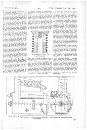
The whole engine is of very stiff construction, and as,*owing to the design of the engine, the material is not massed at any particular points, no difficulties should be caused by unequal expansion of the metals.
The cooling webs which run along the whole length of the crankcase should also assist in stiffening the whole structure.
For mechanical starting, a toothed ring is carried on the periphery of the flywheel, so that if, by any chance, the teeth are damaged a new ring can easily be 'fitted_ The starting motor, is of the magnetic type in which the pinion is drawn into mesh with the toothed ring on the flywheel by magnetic attraction. The sparking plugs are positioned in the sides of the cylinder head casting, and as they are not in any recesses there should be no lag in the rate of flame propagation.