


A Trailer Braking System
Page 66
If you've noticed an error in this article please click here to report it so we can fix it.
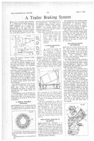
THE ratio of braking effort between a tractor and its trailer should be readily adjustable to suit prevailing road conditions and a scheme for enabling this to be done from the driver's cab forms the subject of patent No. 704,436 (Bendix Aviation Corpora(ion, South Bend, Indiana, U.S.A.). The
scheme also permits 't advance" braking for the trailer.
The tractor brakes are shown at I and these are directly coupled to the main servo cylinder (2). Intake suction provides the power for hydraulic application.
The trailer brakes (3) have in their pipe-line a solenoid-operated valve (4) and a pressure controller (5). The latter is fitted with an adjusting handle within the reach of the driver and is calibrated in inches of mercury. This gives the driver an excellent control over the ratio and enables him to make an instant change should road conditions demand.
The solenoid-operated valve is controlled by a switch (6) on the brakepedal and comes into operation immediately the pedal is moved, thus ensuring that the trailir brakes are applied first.
The foregoing is only the briefest outline of the action which is described much more fully in the patent and is illustrated by drawings of all the main components.
A SIMPLE FLEXIBLE COUPLING I NTENDED for any purpose requiring a cushioned drive, a simple type of coupling is shown in patent No. 704,497
by SocietO • des Fabrications.: Unicorn, 22-24 rue Tiblier Verne, Saint:Etienne, France.
The drawing shows a cross-section of B32 the joint which can be incorporated into any coupled drive. The basic unit is an internally splined female member containing a similarly splined male member. The mating splines form grooves into which are placed a number of round rubber rods (I).
These, when transmitting a drive, are distorted out of round, but as they cannot escape they form a sprung drive. The rubber rods would also accommodate a slight misalignment of the two members.
A VEHICLE HEATING UNIT
A UNIT for heating the
r1 • interior of a vehicle, or for .ventilating it without heat, is shown in patent No. 703,359 (S. Smith and Sons (England), Ltd., rricklewood, London, N.W.2). The unit also provides warm air for demisting the windscreen. The casing contains a radiator (I) fed with hot water from the engine cooling system. Cold air enters via port 2 and some of it passes through the radiator into a chamber at the bottom, whits part of it goes down to a cool chamber located also at the bottom. Two pipes 3 lead to the de-mister whilst the main air outlet is an opening at the bottom, not shown.
The air is controlled by a shaft (4) fitted with flaps which can be set so as to open or close the exits from the hot and cold chambers. The valve shaft is also extended to work a hot-water valve (5) controlling the supply to the radiator. By suitable setting of the valve shaft, the whole unit can be put into or out of operation, or can be made to give any desired mixture of hot and cold air.
PREVENTING SEIZURE IN BEARINGS
1I1OLYBDENUM disulphide is a 'VI substance which has the property of making a bearing surface self-lubricating to some extent, and patent No. 705.067 describes an application which is said (to prevent damage to a bearing in the event of local ot7erheating. The patentee is The Glacier Metal Co., Ltd., 368 Ealing Road, Wembley.
The compound is not actually present in the bearing, but one of its elements, molybdenum, is deposited electrolytically in a thin layer on the surface. The other element, sulphur, is added in powder form to the lubricating oil.
The action is as follows: if, during running, a local hot-spot should come into being, the high local temperature would cause the molybdenum in the bearing and the sulphur in the oil to combine chemically, thus creating the sulphide at the spot at which it will do most good.
THE STEAM ENGINE RE-EMERGES QTEAM as a motive power for road
• -) vehicles has been obsolescent for years, but in view of the contents of • patent No. 704,492, it may yet be seen again. This patent comes from Singer Motors, Ltd., Canterbury Street, Coventry, and discloses a design fOr a roncl-vehicle steam engine.
The engine shown in the drawing is a '-type, having two cylinders in each bank. The general design follows closely internal-combustion practice, being single-acting and provided with overhead inlet and exhaust valves.
For economy, it is important that a steam engine should have its clearance volume kept down to the absolute minimum and the chief feature of the design is the means adopted to ensure this. The idle space is said to be only. 5 per cent, of the cylinder capacity.
The exhaust valve (1) is located over the cylinder bore, and as it is always closed at top dead centre, presents no clearance problem. The inlet valve (2) cannot be similarly treated because the live steam must be applied to its head; if it were applied to its stem side, the steam pressure would blow it open. This valve, therefore, is offset to one side and opens into a recess (3) in the cylinderhead. The recess is fed with live steam via pipe 4. A bore (5) leads from the stem side to the cylinder space; this bore is the only idle space open to the cylinder.