


Dash-board Tyre-pressure Gauge
Page 34
If you've noticed an error in this article please click here to report it so we can fix it.
A Resume of Patent Specifications That Have Recently Been Published. Copies may be Obtained from the Patent Office, Price 11each
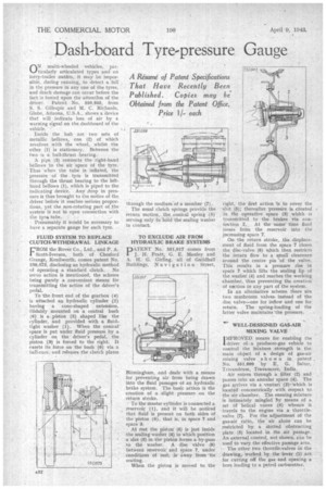
ON. multi-wheeled vehicles, particularly articulated types and on lorry-trailer outfits, it may he impossible, during running, to detect a fall in the pressure in any one of the tyres, and Much damage can occur before the fact is forced upon the attention of the driver. Patent No. 550,945, from S. S. Gillespie and M. C. Richards, Globe, Arizona, U.S.A., shows a device that will indicate loss of air by a warning signal on the. dashboard of the vehicle.
Inside the hub are two sets of metallic bellows, one (2) of which revolves with the wheel, whilst the other (1) is stationary. Between the two is a ballethrust •bearing.
. A lai•Pe (3) connects the right-hand bellows to the air space of the tyre. Thus when the tube is inflated, the pressure of the tyre is transmitted through the thrust bearing to the lefthand bellows (1), which is piped to the indicating device. Any drop in pressure is thus brought to the notice of the driver before it reaches serious proportions, yet the ,non-rotating part of the system is not in open connection with the tyre' tube..
• Presumably it Would be necessary to have a separate gauge for each tyre, FLUID SYSTEM TO REPLACE CLUTCH-WITHDRAWAL LINKAGE CROM the Rover Co., Ltd., and P. A.
Scott-Iversen, both of Chesford Grange, Kenilworth, comes patent No. 550,573, disclosing an hydraulic method of operating a standard clutch. No servo action is mentioned, the scheme being purely a convenient Means irk transmitting the action of the driver's pedal.
To the front end of the gearbox (4) is attached an hydraulic cylinder. (2) having a cone-shaped extension. Slidably mounted on a central bush (6) is a_ piston (3) shaped like the cylinder, and provided with a fluidtight washer (1). When the conical' space is put under fluid pressure by a cylinder on the driver's pedal, the piston (3-) is forced to the right. It exerts its force on the bush (6) via a ball-race, and releases the clutch plates
through the medium of a member (7).
The usual clutch springs provide the return motion, the conical spring (5) serving only to hold the sealing washer in contact TO EXCLUDE AIR FROM HYDRAULIC BRAKE SYSTEMS
PATENT No. 551,017 comes from J. H. Pratt, G. E. Manley and A. H. G. Girling, all of Guildhall Buildings, No vi g a floc Street, Birmingham, and deals with a means for preventing air from being drawn into the fluid passages of an hydraulic. brake system. The basic action is the creation of a slight pressure on the return stroke.
To the master cylinder is connected a .reservoir (1), and it will he noticed that fluid is present on both sides of the 'piston (6), that is, in space 7 and space 3.
At rest the piston (6) is just inside the sealing washer (4) in Which position a skit (5) in the piston forms a by-pass to the washer. A disc valve (8) between reservoir and space 7, under Conditions of rest, is away from its seating.
When the piston is moved to, the
right, the first action is to cover the Tot (5); thereafter pressure is created in the operative space (3) which is transmitted to the brakes via connection 2, . At the same time fluid issues froin the reservoir into the increasing space 7.
On the return stroke, the displacement of fluid from the space 7 closes the disc-valve (8) which then restricts the 'return flow to a small clearance around the centre pin "of the valve, This results in a pressure rise in space 7 ,which lifts the sealing lip of the washer. (4) and reaches the working chamber, thus preventing the creation of suction in any part of the system.
In an alternative scheme there lire two mushroom valves, instead of the disc valve—one for inflow and one for return. The spring-loading of the latter valve maintains-the pressure.
WELL-DESIGNED GAS-AIR MIXING VALVE'
TMPROVED means for enabling the
driver of • a producer-gas vehicle to control the Mixture strength is the main object of a design of gas-air mixing valve shown in patent , No. 551,099 by B. G. Salter, Trivandrum, Travancore, India.
Air enters through a filter (2) and passes into an annular space (4). The gas arrives via a venturi (3).-which is located concentrically with respect to the air chamber. The ensuing mixture is intimately mingled by means of a set of helical vanes (6) whence it travels to the engine via a throttlevalve (7). For the adjustment of the gas-air ratio, the air alone can be restricted by a slotted obstructing plate (5) located in the air passage. An external control, not shown, can he used to vary the' effective passage area.
The other two throttle-valves in. the drawing,. worked by the lever (1) are for cutting off the gas and opening a bore leading to a petrol carburetter,