


LINKING COMPRESSION IU ION WITH PRODUCER GAS
Page 26
Page 27
Page 28
If you've noticed an error in this article please click here to report it so we can fix it.
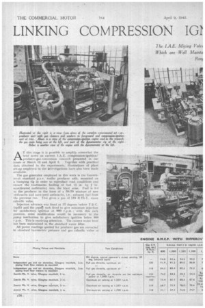
.AT this stage it is pcssible to amplify somewhat the • brief notes on current 1.A.E. compression-ignition/ producer-gas.conversion research presented in our issues of March 12 and April 2. Together with practical data Obtained in the experiments, illustrations of plant set-up employed in the iinve,tigations have also been made
available.
The gas generator employed in this work is the -"Govern/mut standard p.s.v. trailer producer unit, mounted on a bumping rig in order to reproduce road conditions and ensure the continuous feeding of fuel ( in. by 1. in. unactivated anthracite) into the blast zone. Fuel is fed to the 'producer in the form of a 50/50 mixture of new " mthracite and ouce-used anthracite, i.e., unburnt fuel froth the previous rim. This gives a gas of !.18 B.Th.U. mean calorific value.
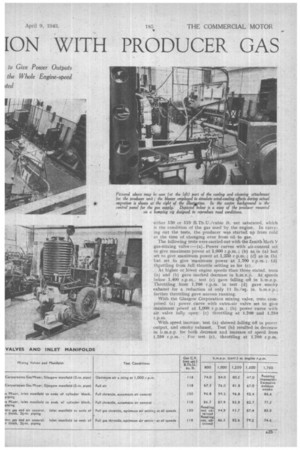
Injection advance was fixed at 33 degrees before T.1.) C. (spill) and the purrit) rack fixed to give minimum injection for satisfactory. ignition at 900 r.p.m. : with this rack position, some modification would be necessary to the pump mechanism to give satisfactory ignition below 900 r.p.m. This is receiving attention. The correct water level has been maintained in the standard water filter. . All power readings quoted for producer gas are corrected to standard barometric prrIssure and gas calorific value of either .130 or -118 B.Th.U./cubic ft. net saturated, which is the condition of the gas used by the engine, in carrying out the tests, the producer was started up from cold at the time of changing over from oil to gas.
The following tests were carried out with the Zenith Mark y gas-mixing valve :-(a), Power curves with air-control set to give maximum power at 1,000 r.p.m.; (b) as in (a) but set to give maximum power at 1,250 r p.m.; (c) as in (b) but set to give 'maximum power at 1,700 r.p.m. ; (d) thiottling from full throttle setting as for (c).
At higher or lower engine speeds than those stated, tests (a) and (h) gave marked decrease in b.m.e.p. At speeds below 1,400 r.p.m., test (c) gave falling off in b.m.e.p. Throttling from 1,700 r.p.m. in test (d) gave smoky exhaust for a reduction of only 11 lb./sq. in. b.m.e.p.; further throttling gave uneven running.
With the Glasgow Corporation mixing valve, tests comprised (a) power curve with extra-air valve set to give maximum power at 1,000 r.p.m. ; (b) power curve with air valve fully open; (c) throttling at 1,700 and 1,250 r.p.m.
With speed increase, test (a) showed falling off in power output, and smoky exhaust. Test (b) resulted in decrease in b.m.e.p. for both decrease and increase of speed from
1,250 r.p.m. For test (c), throttling at 1.700 r.p.m.
resulted in increased power to a maximum b.m.e.p. of about 0 lb./sq. in.; further throttling caused gradual power reduction to about 27 lb./sq. in. b.m.e.p.
The I.A.E. mixing valve, described in our previous issue, gave power outputs which were Well maintained oVer the whole engine-speed range. With good-quality gas, maxi.mum power and torque values superior to those obtained with oil under normal operating conditions could be obtained. Engine power could be controlled by throttling the gas flow to a value representing the minimum required to maintain gas quality, the lower limit being at a b.m.e.p. of about 25 lb./sq. in. Exhaust remained clear throughout the useful throttling range.
A check test on power was conducted, using 2i-in. gas piping, and the inlet manifold used with the I.A.E. gas mixer. Independent air and gas 6ontrols were used. Results are given in the table, and it will be seen that,. for the same gas calorific value and optimum mixture ratio, the I.A.E. gas mixer gives more power throughout, the speed range than the independent air and gas control. It was observed, too, that the inlet-manifold depression was higher throughout the speed range with the two-throttle arrangement than when the I.A.E. mixer was fitted. This difference amounts to as much as 0.5 in. mercury at .the higher speeds, and suggests that the form of air entry of the mixer gives a useful injector effect, thus increasing
the charge weight, In any case; this manifold gives appreciably better results than the Glasgow arrangement, with smaller manifold. depressions throughout the speed range.
Use of the new manifold is partly responsible for the better performance of the I.A.E. mixing valve, as compared with the other two mixers tested. The better characteristics of the I.A.E. mixer over the speed range are, . however, not affected by the manifold arrangement.