


The first part of this, the second article of the
Page 13
Page 14
Page 16
If you've noticed an error in this article please click here to report it so we can fix it.
present series, was published on pages 115-117 of our last issue.
The first part of the present article concluded, on page H7, with a consideration of the gearbox of the Thornyeroft A-T. chassis, and with the fact that very little need for attention, other than its periodic irspection as a safeguard, was necessary. As to the propeller shaft we would emphasize the necessity for replacement of the special leather gaiters, which are provided for each universal joint, after they have beeti removed for inspection. These gaiters are putthere by the maker at sonic expense for 4i. certain parpose. and they should not be discarded in order to save trouble.
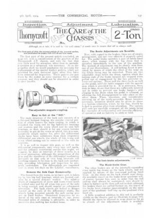
Easy to Get at the "Duff."
The main structure of the back axle consists of a slid-steel bridged forging, the circular central portion of which houses the main casting, in which is mounted the worm and its big ball-thrust bearings and washers and the worm wheel and its own ball bearings, so that, should it for any reason become necessary to get at the worm or wheel, this is a comparatively simple matter for, after the differential shafts have been withdrawn from their respective differential sun wheels, the whole of this worm and worm wheel casting can be removed en Nor with its contents.
11 is as well to inspectthis gear, as well as the differential cemponents, once every now and again, and for ordinary commercial service this might, we eeiggest, be done at intervals of three months as a general precaution, although the proportions of the
ar and the sturdiness of the differential mechanism prretiade us that only at very long intervals will neything require to be done to the back-axle mechanism, providing lubrication and inspection be pro perly undertaken. The differentials are inspected once in every ten days on the L.O.O.C. motorbuses.
Remove the Axle Caps Occasionally.
The thrust from the worm, as we have said, is taken vp by two big ball bearings, which are located end
wise by a special distance washer. The relative deeth of engagement of worm and worm-wheel teeth is settled once and for all when this partof the axle. is being erected, and should require no subsequent alteration. The back wheels are bolted to flanges carried on the ends of the differential shafts, the wheels being mounted outside the axle casing proper on fixed bushes. Occasional inspection by removal of the axle caps at intervals or, say, every thousand miles of running is advisable, in order to aseettein that nothing has worked loose. The Brake Adjustments are Sensible.
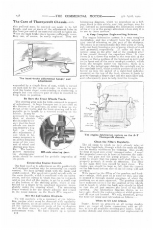
Now, with regard to the brakes, these are of simple arrangement, and are very efficient if properly cared for. The pedal brake operates a pair of fabric-lined shoes, which engage with the big drum that is mounted immediately to the rear of the gearbox. The method of adjustment can be clearly seen from one of our illustrations. A self-locking flynut is provided, by means of which the effect of the wear on the fabric lining may be corrected. There are two adjustable stops below the drum, against which the bottom ends ot the brake hangers are stopped when pulled out of engagement by the two powerful release coil springs. These pull the shoes back, as well as the pedal, until the latter engages with the special stop which is provided for it. It is necessary, front time to time, to see that these are sufficiently screwed out in order to prevent one brake hanger's still clinging to the drum when the pedal is released, so allowing the full disengagement to take place on the otl I Cr drum. When, therefore, any considerable screwing up of the easily-accessible flynut becomes neeessary, attention should also be given to those tvvo bottom setscrews, which, by the way, should be loeked in position after their alteration. The various pull rods are carefully arranged, all the joints being flee examples of workmanship and ensuring efficiency of operation and no liability to atiek or bind.
The other brakes are of the internally-expanding class inside big drums on the back wheels, and are applied by means of the now-usual pull-up hand lever. As the shoes on the back wheels wear down, the available travel on the brake-lever quadrant will, of course, become less, and, in order that the full pull-up shall always be maintained, care should be taken to tighten up the first pull rod so that, although the brakes shoes are pulled further on, the travel of the brake lever remains approximately on the same part of the quadrant—half way up the quadrant when hard on.
A little weighted addition to this rod is perfectly visible on the chassis, and we illustrate it (page 13B), Should the shoes he allowed to wear down so far as to absorb all the adjustment which is available
this pull-rod must be screwed out again to its full length, and one or more of the adjustment holes in the front jaw end of the next rod should be taken up. When the back brake shoes become sufficiently worn, they can, of course, be easily replaced. They are expanded by a. simple form of cam, which is turned on each side by the twin pull rods. In order to prevent the brake shoes' cross-winding or chattering, a simple but very effective pair of clips is mounted to keep them in position.
Be Sure the Front Wheels Track.
The steering gear calls for little comntent in respect of adjustment. A large hexagon nut is Provided at the bottom of its gearcase, in order to take up tie thrust of the worm, and the front steering red is adjustable as to length by a screwed coupling on the ()aside. It may be necessary to lengcane' then or shorten ..aeek this in order to ensure that the front wheels are tracking properly; neglect to effect this adjustment if and when it becomes necessary is an all-too-frequent cause of tire wear and of wheel and steering-gear trouble. The leather gaiters enclosing the steering-gear joints should be removed for periodic inspection of the joints.
Off-side steering gear.
Concerning Engine Control.
Our final word as to adjustment on this particularly well-designed machine may be concerning the engine control. We have already dealt with the brake and clutch control. The accelerator pedal acts directly on the main throttle, which is combined with the carburetter, and the extent to which this can be released, and so can shut off the engine, is set by a small stop at the bottom of the steering pillar, which is controlled by a finger lever, quadrant mounted, immediately under the steering wheel. The remaining finger control is for the simple advance and i etard in the usual manner on the Bosch ZIT4 magneto.
See the Lubrication Diagram.
We will conclude with a summary of the lubrication routine which must be observed with regularity on this chassis, as on all others, if it be desired that all the various component parts of the mechanism may do their share of work efficiently and without unnecessary wear. We have drawn up a special 012 lubricating diagram, which we reproduce as a fullpage block in this article, and this, perhaps, may be put forward as summarizing the lubrication routine of the driver or the garage attendant whose duty it is to see to these matters.
A Very Complete Engine-oiling Scheme.
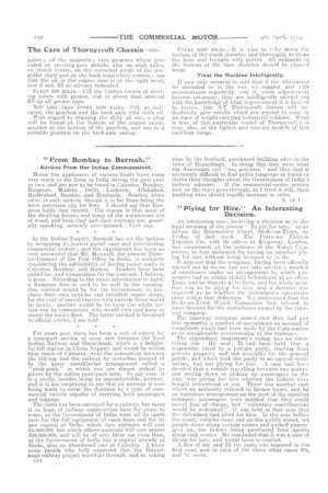
The engine lubrication system is a very complete installation, and has evidently been the subject of very careful scheming on the part of the designer. The pump is an exceptionally-fine little piece of work, a die-cast body housing a pair of pump wheels of steel and gunmetal, respectively. It sucks oil from a special sump at the after end of the crankpit after it has passed through the capacious filter. It then forces it to a. three-way union On the near side of the engine, so that a portion of the lubriwnt is delivered to the front end of the main crank-pit conduit, which feeds the troughs under the big-ends ; there is a, shunt to the helical gear driving the camshaft and to the camshaft itself, whilst another portion of the oil is forced up into the jacket of a sight-feed indicator mounted on the top of the dash, whence it feeds by gravity through a larger pipe into the main filler box, and subsequently goes to help feed the troughs.
Clean the Filters Regularly.
The oil sump to which we have already referred has a big hand-hole, through which the main oil filter can be readily withdrawn for cleaning. This should be done at least once every thousand miles. A small flat gunmetal reservoir is inserted between the mainsump feed pipe and the pump proper. This is in order to ensure that the pump itself shall always be properly primed; it needs no attention. The filter in the main filler box should be kept clean. The engine case should be kept so full, that the trycock on the left-hand bottom side of the oil sump will just overflow.
With regard to the filling of the gearbox and backaxle casings, thick gear oil is used for this, and this is poured in through special openings, of which the positions are at once apparent. The gearbox should have sufficient oil in it for the smallest of the wheels just to touch it, whilst the back axle should be filled so that. the oil just reaches the level of the filler opening. Our lubrication diagram shows, as we have said, clearly the various points at which greaser; and oil cups are located. We will, therefore, greup the need for oiling and lubrication as follows
When to Oil and Grease.
DA ILY. -Screw up greasers on all spring shackle pins ; go round all brake connections with an oil. can, as also all available steering-gear joints, brakecontrol details and clutch-control and engine-control
joints ; oil the magneto ; turn greasers where provided on steering-gear details, also on stub axles, on clutch centre, on the universal joints of the propeller shaft and on the back road-wheel centres ; see that the oil in the engine case is at the right level, and if not, fill as already indicated
EVERY 500 aleas.—Eill the leather covers of steerJug joints with grease, and at about that interval fill up all grease cups.
NOT LESS THAN EVERY 1000 MILES.—Fill, as indicated, the gearbox and the back axle with thick oil.
With regard to draining the dirty oil out, a plug will be found at the bottom of the engine stunp, another at the bottom of the gearbox, and one in a suitable position on the back-axle casieg.
EVERY 5000 MILES. It is wise to take down the bottom of the crank chamber and thoroughly to clean the base and troughs with petrol. All sediment in the bottom of the base chamber should be eleaud away,
Treat the Machine Intelligently.
It now only remains to wad that if the lubrication be attended to in the way we suggest and with conscientious regularity, and if when .adjustments become necessary, they are intelligently earrikd nut with the knowledge of what improvement it is desired to secure, this A-T Thornycroft chassis will andoubtealy give results which are second to none in its class of weight-carrying industrial vehicles. What is true of this particular model of Thornycroft's is true, also, of the lighter and heavier models of this excellent range.