


Patents Completed,
Page 28
If you've noticed an error in this article please click here to report it so we can fix it.
CLUTCH MECHANISM.—Cadett.— No. 5,715, dated 9th March, 1907.—This invention relates to clutch mechanism for constant-mesh, change-speed gearing. A hollow driving shaft (1) is provided on which the loose gear wheels (2) and free wheel clutches (3) are mounted. The loose member of each clutch consists of a drum (4) having end plates (5) to which the loose gear wheels (2) are connected by screws (6). The loose wheels (2) and the drum (4) are furnished with ball bearings (7) so as to minimise friction when they are running free on the shaft (1). The inner periphery of each of the drums (4) is furnished with ratchet teeth (8) whieh are adapted to be engaged by a pawl (9) pivoted at 10 to the plate (11). The pawl is held in the path of the ratchet teeth (8) by a spring-controlled plunger (12). The pawl (9) is adapted to be held out of engagement with the ratchet tecth (8) by means of a sliding link (16) so as to leave the drum (4), and its corresponding gear wheel, free on the shaft. One end of tha link (16) has a claw (17) which engages a recess (IS) in the pawl (9), whilst the other end is furnished with an arm (19) which projects through radial slots in the plate (11) and the hollow shaft (1) and engages a cam groove (20) that is formed in a rod (21) which slides within the hollow shaft (1). The various loose gear wheels are clutched to the shaft (1), as desired, by the manipulation of the change-speed lever which operates the sliding loci (21) so as to cause the cam groove therein to raise the link (16) in the fixed member (n) of the corresponding clutch. This allows the spring-controlled plunger (12) to raise its pawl (9) and come into contact with the ratchet teeth on the drum (4).
POWER DRIVING MECHANISM.— Daimler Motorea Gesellschaft.—No. 6,202/07, dated (under Convention), 19th
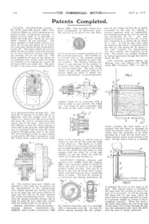
March, 1906.—This invention relates to a novel arrangement of differential gear. The member (c) is driven from the shaft (a) by means of a toothed coupling (b) of the universal-joint type. The member (c) is recessed and in the recesses planet wheels (d, f) are arranged to gear with one another. The distance between the wheel (f) and the axis of the member (c) is greater than that between, the wheels e-e') and the same axis. The teeth of the wheels (d) gear with internal teeth on a hollow wheel (g) which is rigidly conceded to the shaft (3). A second internally toothed wheel (k) is connected with a hollow shaft (1) and encloses the wheel (g). The wheel (3) gears internally with the teeth of the Wane wheel (f). The teeth in the ring (3), as will be seen in Figure 2, are out of line with the teeth of the wheel (g). The shafts (n, 1) carry bevel wheels (7, as) of equal sire and they are arranged at snc1.1 an angle to the centre line of the vehicle that the wheel (I) only engages with the wheel (p) of the axle member e;t) and the wheel (m) with the wheel (q) of the axle member (a).
RESILIENT WHEEL.—Burtart and Another.—No. 17,902, dated 6th August, 1907.—This invention relates to wheels in which the axle is fixed in an eccentric position within the hub. The axle (1) is keyed) to the hub (3) which latter is provided with ball bearings (5) to permit the wheel to rotate. The huh (3) consists of a cylindrical box having projections (8, 11) integral therewith, and it is provided with a removable cover (4). An arm (7), which extends between the two projec lions (8, 11) within the hub (3), is rigid13 connected to the axle (1). Blocks o resilient material, such as indiarubber are mounted between the arm (7) and th( two projections (8, 11). An arm which is secured to the hub (3), is pivot ally connected to a spring (9) by means of a rod. It will be seen that, wher the centre of the wheel is displaced roune the axle (1), the spring (9), by means cr the rod, controls its displacement and thus absorbs the vibrations of thi axle. The shocks are further deadenec by being transmitted through the resilien blocks (9, 12). .
LOW WATER ALARM—Bellies an llorcom, Ltd., and Others.—No. 26,159 dated 26th November, 1907.—A tank (a
which contains the feed water to b pumped into the boiler is arranged be neath the driver's seat (d). This tank i closed with the exception of an orific provided by a tube (5), the lower end c which extends nearly to the bottom of th tank. In this tube a float (c) is inserter to indicate the level of the water in Oa tank. The exhaust steam is admitted t the tank from the conduit (a) and a ver pipe (f) is provided. It will be seen the the space-left in the tank above th water will be occupied normally by stem at a pressure slightly in excess of the al mospheric pressure. When the level c the water sinks below the end of the pip (3) the steam will escape through the pip into the atmosphere and warn the drive that the tank is nearly exhausted.