


Dynamos, 2
Page 51
If you've noticed an error in this article please click here to report it so we can fix it.
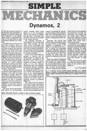
IN THE last article the theory of the dynamo was considered. In practice the dynamo takes the form illustrated in the photo, which shows a dismantled dynamo of the type fitted to light commercial vehicles and motor cars.
It consists of the armature, the part that revolves, which is made up of a slotted laminated iron core on which the coils are wound, a cylindrical yoke, two end covers and the field windings. The coils on the armature are connected to the copper segments which form the commutator at one end of the armature. The shaft at the commutator end of the armature usually revolves in a plain sintered bronze bush, while at the other end a ball race is fitted to cater for the heavier stresses imposed by the V driving belt.
The two field coils are wound on soft iron pole pieces and are secured to the yoke by large countersunk screws. Some of the current produced by the dynamo is shunted across the field windings so that a magnetic field is produced. Residual magnetism in the pole pieces is sufficient to start the machine charging when it first starts to revolve.
The cover at the commutator end carries the spring-loaded
carbon brushes which press lightly on to the commutator. One of the brushes is earthed and the other is insulated from the outer cover and is connected to the output terminal.
The complete assembly is held together by two long bolts which pass through , the end plate at the commutator and screw into the cover at the pulley end. A fan is usually provided on the inner side of the drive pulley to force air through the dynamo for cooling purposes.
There is very little difference between a dynamo and an electric motor. If a dynamo was permanently connected to the battery, when the engine stopped the battery would be trying to turn the dynamo, discharging itself and probably burning the dynamo windings. To prevent this happening a relay, generally known as a cutout, is fitted. This basically consists of an electromagnetic switch which closes when the dynamo is charging, but opens, breaking the circuit, when no charging current is produced. (Figure 1).
The output from the dynamo must be controlled, otherwise at high engine speed the current generated would be so high that the electrical equipment on the vehicle would be destroyed. The
output is controlled by regulating the strength of the magnetic field. Put in simple terms this is done by one or two relays very similar in appearance to the cutout.
Generally, the cut-out and control relays are housed under the same cover. In the voltage regulator, a resistance is inserted in the field circuit and a pair of points are connected across the resistance. When the contacts are open the resistance is connected into the field winding but when they are closed the resistance is shunted out.
When the engine is stoppped and the dynamo is not charging the contacts are closed {unlike the cut-out where they are open when the dynamo is not charging). As soon as the dynamo starts to charge and the voltage
rises, the pull of the electromE net becomes stronger un• eventually, the contact poir are pulled apart. When tl occurs the resistance is insert in the field winding circuit, t voltage then drops and t points close again.
Immediately the voltage ris the points are again opened brating as often as ND times p second, providing an avera voltage so adjusted as to ke the battery properly charged. second, and similar device, t current regulator, which lirn the maximum current outp from the dynamo, is usua fitted.
In the next article the alterr tor, which has largely taken t place of the dynamo, will looked at.
by Precept(