


COMPRESSORS FOR GAS TURBINES
Page 28
Page 29
If you've noticed an error in this article please click here to report it so we can fix it.
MOTOR manufacturers, sensing themselves to be on the brink of a new age in prime movers, but seeing few immediate advantages, are, in some cases, making tentative experiments more with a view to familiarizing themselves with the new problem, than with the intention of considering large-scale production. That turbines will eventually power road vehicles is a foregone conclusion. but development engineers are, to a large extent, in advance of metallurgists and power-transmission designers.
For road-vehicle use the gas turbine is at a disadvantage. as compared with aircraft units, in having to operate at ground level. In an aeroplane a degree of supercharge is obtained from the ramming of the air into the compressor orifice by the forward motion of machine. As thermal efficiency is dependent on the difference between the temperature of combustion and that of the atmosphere, the higher the altitude, the more favourable this becomes.
Multi-stage Compression The trend of development for marine and stationary power plants is in the direction of multi-stage compression and expansion, with air coolers and heat interchangers. A power plant on these lines, in comparison with other forms of power delivery, is compact and tight, but outputs are
well above 2,000 h.p. Obviously, complications of this nature cannot be allowed in road-vehicle work, where an output of 100 h.h.p. is more in keeping. Even in this size the work involved would be in the nature of a watchmaking job, and as the largest possible components compatible with efficiency are desirable, to split the output over several separate turbines would he totally impracticable.
A road-vehicle turbine would, therefore, not be likely to differ in principle from the aircraft types, which comprise a compressor delivering air to a combustion chamber. Fuel is there injected and burned, raising the temperature, and hence the volume of the air when it is passed to the turbine. To ensure a reasonable economy, a heat interchanges would be essential so that the exhaust gases would raise the temperature of the ingoing air before entering the combustion chamber.
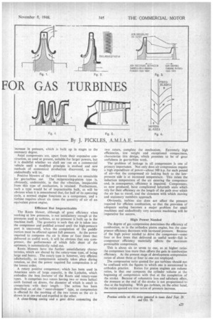
High Peripheral Velocity Compression may be accomplished in several ways, of which. the most obvious is that embodied in the Whittle turbine. This is of the centrifugal type and operates at about 17.000 rsp.m. (Fig. 1). Compressors of this kind are, however, of doubtful value for small units, as the delivery pressure is largely dependent on the peripheral velocity. In consequence, still higher rotational speeds must be used If the diameter is to be reduced, thereby making it more in keeping with the smaller power output.
To use two or more stages. with the idea of reducing rotational speed, introduces further difficulty, as the bursting stress in the impeller disc prohibits the boring of a hole for shaft mounting. The shaft must, therefore, be flanged and bolted to the impeller, so that, with multiple stages, it is difficult to apply satisfactory seals to prevent loss of pressure. The prevention of such leakage is doubly important in that, not only is the work performed in compression lost, but the air returning to the low-pressure side is at a high temperature, causing the air entering the compressor to be heated and thereby calling for extra work in compression (Fig. 2).
Perfect Balance Essential In this type of machine the pressure falls off rapidly with even a small drop in the speed. This is quite satisfactory for a more or less constant-speed machine, but of little use when the speed is subject to continuous variation.
• The greatest disadvantage, however, is that, to obtain the highly accurate balance required for smooth running, the impeller must be machined all over its complicated form. and to reduce the chance of failure, a high finish is essential. Even a one-in-a-thousand chance of disruption could not be risked in a vehicle required to operate on a road, so that it is hardly possible that a centrifugal compressor will be incorporated in a machine of the type envisaged.
Centrifugal compressors, as used on the Whittle machines, and subsequently embodied in the Rolls-Royce Derwent and Nene types, are double-sided, in that vanes are formed on both sides of the impeller disc. This construction enables
large masses of air to be moved with comparatively small components. De Havilland, on the other hand, has stood firm to the single-sided impeller (Fig. 3), holding that the advantages thus obtained more than counteract any disadvantage which may exist.
End-thrust, de Havilland engineers claim, is minimized. because the turbine thrust works in a direction opposite to that of the compressor, whereas, in the double-sided type, although the impeller is balanced in itself, the result is unbalanced end-thrust from the turbine. Further, the air entry is much less tortuous than with the double-sided type, thus providing for a somewhat higher efficiency.
Seating Complicates Assembly Multi-stage centrifugal compressors are a possible method of obtaining any required pressure at a reduced speed, but any fall in speed produces an abnormal pressure loss, so that even with several stages, quite high speeds are still necessary (Fig. 4). The complication necessary to permit the components to be assembled is extraordinarily great, because of the careful sealing required to • maintain the pressure. and the air path becomes tortuous, if the extra complication of inter-stage cooling can be resorted to, then multi-stage compression is undoubtedly desirable, in that the efficiency is improved.
German preference has been universally for the axial turbine compressor, and a unit of this type was employed in the Brown Boveri locomotive (Fig. 4). Such compressors have the advantage of a relatively high efficiency, but as they depend for the degree of pressure rise on linear blade velocity, high rotational speeds, or an abnormal number of pressure stages, must be countenanced.
As with longitudinal dimensions, very accurate workmanship is necessary to maintain the clearances at the minimum. Leakage is limited on large machines by complicated labyrinth seals, and it will be obvious that the degree of effectiveness is dependent on the length of the leakage path. On a 100 b.h.p. unit this cannot be reduced, as pressures, unlike the dimensions, are not, unfortunately, scaled down.
The Axial System Axial compressors comprise alternate rings of moving and stationary blades, the pressure being built up in the lastnamed (Fig. 6). Air is set in motion by the moving blades in the manner of an airscrew, and the angle and speed are so chosen that the air is directed on to the fixed blades without shock. The blades are designed so that the crosssectional area of the path between adjacent members is smaller at the point of entry than at the exit.
It is a principle in hydraulics, known as Bernoulli's theorem, that a fluid in motion may have a given amount of energy—kinetic, pressure, potential or any combination— and by varying the area of its path, energy may be converted into one form or another. Kinetic energy is added to the air by the moving blades, in addition tceany pressure. energy it may have.
No energy, however, can be added or taken away in the passage between the fixed blades, so that, as the speed of the air must fall as the area between the blades increases, there must be a corresponding decrease in kinetic energy (Fig. 6). The fall in air speed must, therefore, result in an
increase in pressure, which is built up in stages to the necessary degree.
Axial compressors are, apart from their expensive construction, as used at present, suitable for larger powers, but it is doubtful whether we shall see one on a commercial vehicle until a modified principle is evolved and new methods of economical production discovered, as they undoubtedly will be.
Positive blowers of the well-known forms are unsuitable for gas-turbine use. The reciprocating-piston type is, obviously, undesirable, in that the vibration, inseparable from this type of mechanism, is retained. Furthermore, such a type would be of impracticable bulk, as will be obvious when it is remembered that, for half of its operating cycle, a normal engine functions as a compressor, and a turbine requires about six times the quantity of air of an equivalent piston engine.
Efficient But Impracticable The Roots blower, although of great efficiency when working at low pressures, is not satisfactory enough at the pressures used in turbines, as no pressure is built up in the machine itself. The geometry is such that air is taken into the compressor and paddled around until the high-pressure port is uncovered, when the completion of the paddle motion must be effected against full pressure. As the power required to compress the air is three or four times that delivered as useful work, it will be obvious that any compressor, the performance of which falls short of the optimum, is automatically ruled out.
Roots blowers have the further unsatisfactory characteristics, which are shared by the rotary-vane type, of being large and heavy. The rotary type is however, very efficient adiabatically, as compression actually takes place during rotation, so that the power required for compression is of the lowest order.
A rotary positive compressor, which has been used in American units of large capacity, is the Lysholm, which embodies the best features-of the Roots and rotary-vane types. It comprises two rotors having two or more helical teeth formed on drums, the diameter of which is small in. comparison with their length. The action has been described as of the " meat-chopper" type, as compression is effected by the meshing of the two rotors as the air is drawn in at one end and expelled at the other.
A close-fitting casing and a gear drive connecting the two rotors, complete the mechanism. Extremely high efficiencies, low weight and exceptional compactness, characterize this design, which promises to be of great usefulness in gas-turbine work.
The problem of leakage in all compressors is one of primary importance. Not only does air compression require a high expenditure of power—about 100 h.p. for each pound of air—but the compressed air leaking back to the lowpressure side is at increased temperature. This raises the induction temperature of the air entering the compressor and, in consequence, efficiency is impaired. Compressors, as now produced, have complicated labyrinth seals which rely for their efficiency on the length of the path over which the air has to travel, and the closeness with which moving and stationary members approach.
Obviously, turbine size does not affect the pressure required for efficient combustion, so that the provision of adequate sealing becomes a major problem for small machines. and undoubtedly very accurate machining will be imperative for success.
High Power Needed • The degree of gas compression determines the efficiency of combustion, as in the orthodox piston engine, but the compressor efficiency decreases with increased pressure. Because of the high power needed to drive the compressor—some four or five times that delivered as useful work--fall in compressor efficiency materially affects the maximum permissible compression.
This is about six or seven to one, as at higher ratio,: the compressor loss more than offsets the gain in combustion efficiency. At the present stage of development compression ratios of about three or four to one are employed.
The compression ratio quoted for gas turbines should not be confused with the figures to which one is accustomed in
orthodox practice. Ratios for piston engines are volume ratios, in that one compares the cylinder volume at the beginning of compression with that at the completion of the stroke. Because of volumetric loss and adiabatic effect, the pressure at the end of the-stroke is not proportional to that at the beginning. With gas turbines, on the other hand,
the ratios quoted are true ratios of pressure increase. .