


Clutch Engagement By Pedal Pressure
Page 34
If you've noticed an error in this article please click here to report it so we can fix it.
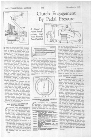
THAT the driver can obtain a much nicer sense of " feel " with a clutch made to engage by pressing down the pedal, is one of the claims made for a design of this nature shown in patent No. 526,657. The invention comes from an authority on clutch design, Borg-Warner Corp., Chicago, U.S.A.
The interior of the clutch mechanism differs little from normal, except that the fingers are arranged so that the plates are parted by springs instead of being engaged thereby. Externally, a control arm (5) mounted on a ballpivot acts, at one end, on the thrust washer, whilst the other end embraces a rod (4) and is moved by the compression of a spring (6). The rod (4) may be regarded as being directly coupled to the clutch pedal, the parallel-link motion (3) being used only to prevent " waggle "of the pedal due to movement of the engine on its resilient mounting.
In operation, foot pressure on the pedal pulls on the rod (4) which in turn moves the lever (5) via the spring, The clutch. is thus engaged, the pedal being held in the down position by means of a pawl (2) hooking on to a floor-plate. The pawl is fully under the driver's control, being operated by rocking the pivoted pedal-plate (1). Toe pressure engages the pawl, heel pressure releases it. It is also claimed that the scheme allows a more favourable leverage to be used, so that a pedal pressure of only 35 lb can develop a plate pressure of 1,200 lb.
FOR QUICKLY STARTING-UP GAS PRODUCERS
ANigniting torch for gas producers is shown in patent No. 526,475 by the Gas Light and Coke Co., Ltd., and H. Lawrence, 84, Horseferry Road, London, The device consists of a perforated sheet-metal casing containing a smaller tube, also perforated, the intervening space being packed with absorbent asbestos. A wooden handle (not shown) is attached to a convenient point.
• In operation, the inner tube is packed with charcoal or anthracite, and the asbestos soaked with paraffin and lit. The nose (1) which has a perforated 'end is then inserted into the tuyere of the producer, and the engine started on petrol. The flaming paraffin ignites the tube of charcoal, and lo soon as this is well alight, the operative withdraws the torch, holding it by the handle, and pours the burning charcoal into the tuyere. This then ignites the charge.
Whilst the device is most suitable for producers having a downwardly pointing,tuyere, it can be used for the horizontal-tuyere type if this be adapted by providing an upwardly painting air intake.
HARNESSING AIR FOR VEHICLE SUSPENSION
AIR suspension or "pneumatic springing " is the subject of patent No. 526.480 by General Motors Corp..
Detroit, Mich., U.S.A. Though the patent is concerned with the construe tion of the air-container, it illustrates also the method of mounting; this is shown in the drawing.
The pneumatic system comprises a. pair of hollow rubber cushions (4) reinforced with cord or fabric. The pad thus formed is closed at the bottom, but a central passage connects both bags with a metal air-reservoir (3). *The bottom metal plate is clamped to a " tishbone " link (5) whilst the upper end, that is, the metal reservoir, is bolted to the chassis. An upper link (1) completes the parallelagram through the medium of a shock absorber (2).
The sYstem may be made adjustable to suit various loads by interposing between the bag and the reservoir a valve to control the rate of response.
NEW DESIGN OF TWO-LEADING. SHOE BRAKE
A'improvement in the type of brake in which one shoe at -least is allowed limited circumferential movement is the subject of patent No. 526,594 from Autom6tive Products Co., Ltd., and others, Brock House, Langham Street, London, W.1.
The drawing illustrates in a simple form the basic principle, though the actual construction may differ. Between one pair of adjacent shoe-ends is a spreading device (1), ptobably hydraulic, whilst the opposite ends are separated by a fixed abutment (4). One end of the' spreader engages the right-hand shoe directly at the point (2) and indirectly on the other end (3) via a pair of coupled bell-cranks (7) and a push-rod (5). The upper bellcrank is pivoted on a pin (6) on the left-hand shoe, but the lower hell-crank piVots on the back-plate.
In operation, the right-hand shoe with its linkage is able to move circumferentially, and, when rotation is anti-clockwise, it can transfer its reaction to the opposite shoe via the spreader piston. With clockwise rotation the abutment takes the reaction; the only transfer is that via the push rod. Thus, in the first case, both shoes act as leading shoes, but, in the latter, only the right-hand shoe operates as a leader and the other functions like the secondary shoe of a self-energizing system.