


A NEW KEROSENE VAPORIZER.
Page 10
Page 11
If you've noticed an error in this article please click here to report it so we can fix it.
A Method of Using Artificial Heat in the Making of the Gas.
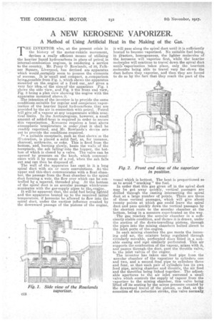
THE INVENTOR who, at the present crisis in the history of the motor-vehicle movement, devises a really efficient means of utilizing the heavier liquid hydrocarbons in place of petrol, in internal-combustion engines, is rendering a service to the country. Mr. Percy 0 Rowlands, of 30, Falkner Square, Liverpool, has devised am apparatus which wouldocertainly seem to possess the elements of success. It is' small and compact, a...comparison being,possible from Fig. 1, which shows the apparatus rriounted on the, engine of a Ford car,iand gives a very fair idea. of the sizel of' the apparatus IFig. I. shows the side view, and Fig. 2 the front end view, Fig. 3 being a plan view showing the engine with the apparatus mounted' above, it.. . The intention.of the inventor is to provide the same conditions. suitable for regular and competent vapor_ ization of the heavier liquid hydrocarbons that are provided by the air in connection with petrol.Petrol. will give off a vapour at any temperature within macHeal limits. In the Areticeregions. however, a small amount of addediheat is required in order to. secure this vaporization.. Kerosene requires a heat above atmospheric temperature in order „that it shall be readily .vaporized, and Mr. Rowla,nds's device sets
out to provide the conditions required. .
7,, a suitable receptacle, such as that shown in the iTheitration, is placed a solid fuel, as, for instance, charcoal, anthracite, or coke. This is fired from the bottom, and, burning slowly; heats the walls of the receptacle, the ash falling' into the hopper' the bottom of which is closed by a valve. The valve can be opened by pressure on the knob, which communicates with it by means of a rod, when the ash falls
out and can then be disposed of. .
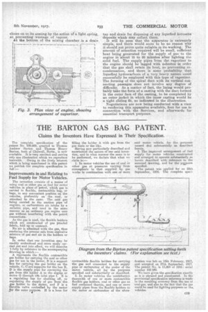
The wall of the apparatus has cast in it 'a long spiral duct with six or more convolutions. Atrthe upper end this duct communicates with a float chamber, the passage from the float chamber to the spiral duct forming a weir, the flow over which can be controlled by a tapered, thread-ed plug. At the bottom of the spiral duct is an annular passage whichecorn. municates with the gas-supply pipes to the,eng.ine„ . It will be apparent that the solid fuel beingighted . and the' apparatusheated up to the required initial temperature. if kerosene be allowed to flow i to the 1
spiral duct, under the suction influence created by the downward passage of the pistons of the engine, it will pass along the spiral duct until it is sufficiently heated to become vaporized. No suitable fuel being, in fractice, homogeneous, the lighter molecules of the kerosene will vaporize first, while the heavier molecules will continue to travel down the spiral duct until. vaporization takes place, only. the heaviest molecules being able to travel very far .down the duct before they vaporize, and then they are forced to do so by the fact that they reach the part of the vessel which is hottest. The heat is proportioned so as to avoid "cracking" the fuel. . " In order that this gas given off in the spiral duct may be got away quickly, vertical passages are drilled through the casting intersecting the spiral duct at a large .number of points. There are three of these vertical passages, which will give about twenty points at which gas could leave the spiral duct and pass quickly down the vertical passages by the shortest route to the annular chamber at the bottom, being in a measure superheated on the.way. The gas reaches the annular chamber in a sufficiently stable condition, and thence it is drawn, under the suction of the down-travelling pistons, through the pipes into the mixing chambers bolted direct to the inlet ports of the-engine.
In each mixing chamber the gas meets the incoming cold air, the mixture being regulated through circularly movable, perforated discs fitted in a suitable casing and seiat similarly. perforated. This air supports the combustion of the vapour, mixes with it, and •passes through-the duct, past the throttle valve,
to the inlet valves of the engine. 4, The The inventor has taken one 'feed pipe from the annular chamber of the vaporizer to cylinders one and two, and a sebond feed pipe to cylinders three and four, so that 'each pair of cylinders ha its own feed pipe, mixing chamber and thr-ottle, the air feed and the throttles being linked together. The adjustable apertures to the air inlet surround a small valve which controls the supply 'of vapour from the vaporizer to the mixing chamber, this valve being lifted off its seating by the minus pressure created by the downward travel of the pistons, so that, at the cessation of the induction stroke, this valve normally,
closes on to its seating by the. a-ction of a light spring, so preventing wastage of vapour.— • . At the bottom of the mixing chamber is a drain. tap and drain for disposing of any liquefied kerosene deposits which may collect there. It will be seen that the apparatus is extremely simple, and there would seem to be no reason why it should not prove quite reliable in its working. The amount of attention required will be small, sufficient heat being generated for the supply of gas to the engine in about 15 to 20 Minutes after lighting the solid fuel. The supply pipes from the Vaporizer to the engine should be lagged with asbestos in order that the gas shall retain its heat, so preventing recondensation, and there is some probability that liquefied hydrocarbons of a very heavy nature could successfully be employed with this type of vaporizer. The forming of the spiral duct with its vertical connecting passages does not involve any degree of difficulty. As a matter of fact, the lining would probably take the form of a casting with the duct formed in the outer face of the casting, to be completed by an outer jacket in which the inner casting would be is tight sliding fit, as indicated in the illustration.
Negotiations are now being conducted with a view to rendering this apparatus available, first for use in connection with the Services, and afterwards for essential transport purposes.