


Adjustable Pre combustion Chamber
Page 68
If you've noticed an error in this article please click here to report it so we can fix it.
TO permit the combustion charac teristics and the compression ratio of an engine to be changed with little difficulty is the aim of a cylinder-head shown in patent No. 810,288. Although illustrated as applied to an oil engine, the patent covers also spark-ignited engines. (A. Smith and A. Sidney, both of Saltdean Vale, Saltdean, Brighton.) The combustion chamber is offset to one side of the cylinder and has a parallel bore. A separate plug is inserted to create a combustion space (1) of any desired configuration; the drawing shows one having a tangential inlet to a small chamber, thus giving a high compression. The plug is held by the 'clamping force applied to the injector (2). Another drawing (not published) shows the bore almost . empty; the plug has only a short spigot at the top, thus lowering compression.
SELF-ADVANCING INJECTION
PATENT No. 810,227 shows an injection pump in which the injection timing is automatically advanced with increasing delivery. The pump described is of the type in which the pumping units lie parallel with the spindle and are worked in succession by a single-lobed cam. (Mono-Cam, Ltd., W. Friedlander and Z. Miracki, all of Oak Lane, East Finchley, London, N.2.) Referring to the drawing, the cam (1) works thrust members (2) each of which carries a conical roller, bearing On the 6.m. The cam has a tubular extension (3) which is internally splined to fit the splines on the inner end of the driving spindle (4). Both sets of splines arehelical and mate as shown at 5.
-The driving spindle (4) has parallel splines (6) on its outer end; they permit the spindle to slide. The spindle is moved to the left (against a spring 7) by fuel pressure acting on the upper face of a piston (8). The pressure used for this originates in the spilled fuel from the pump units, and the movement of the piston, by virtue of the helical joint, moves the cam in an angular direction. Quantitative control of output is given by an enclosing sleeve (9) around each plunger, the position of which can be adjusted by an external control.
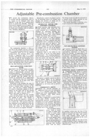
HYDRAULIC MOTOR FOR POWERED STEERING APID response, high operating force and freedom from noise are the virtues claimed for a hydraulic motor designed for operating steering gear and described in patent No. 806,615. (Thompson Products Inc., 23555 Euclid Avenue, Cleveland, Ohio, U.S.A.).
The unit consists of a pair of pistons (I and 2) working in the same cylinder. , The pistons are quite separate and each ' is 'provided with a tail-piece (3 and 4) which has rack teeth cut upon it. The right-hand rack engages with the underside of a pinion (5) and the left-hand one engages with the top of the pinion; this is not shown in the drawing owing
to the cut-away (6). • -• • Hydraulic fluid is fed either to the middle space or to the two outer spaces simultaneously. The resulting approaching or receding motion of the two pistons turns the pinion and shaft (7), which in turn mcive,the steering linkage.
The pinion is Slightly tapered as shown and is loaded lightly in an endwise direction by a spring in the housing (8). This is said to maintain close tooth engagement at all times and so prevent back-lash. ” • . EMERGENCY SERVO
DATENT . No. 810,328 describes an
additional brake servo for emergency use. .. It is intended both. for heavy, vehicles and trailer cornbin.ations. (The Talco Company', 2685 State • Street,. Hamden, Conn., U.S.A.) .
The idea is applicable to power brakes of all types whether vacuum, air or hydraulically operated. It consists of the provision of an extra cylinder and piston. as illustrated in the drawing. The piston is connected to'some point on the braking linkage and normally lies inactive at the left-hand end of the cylinder.
The emergency power comes from a small cartridge (1) filled with cordite or some other slow burning propellent. The charge is electrically ignited when the driver closes a switch and the piston is then forced to the right, applying full braking force with no delay. The firing circuit can also be actuated by a second switch which operates in the event of a trailer break-away.
The patent describes a metering valve to give progressive brake application.
ignition system in which there are no.moving parts other than a simple engine-driven alternator is shown in patent No. 810,308. A single pulse from the alternator is applied to a " peaking " transformer. This gives such a rapid flux change that the necessary high-voltage ". pulse is given by the secondary winding without the need for any breaking ofthe circuit. The scheme calls for as many . transformers as there are engine cylinders, because there is no distributor. The Patent comes from A. Gurviz, 8 Via S. Sisto, Milan, Italy.
IMPROVED SOLEX CARBURETTER .
I—I A CARBURETTER shown in patent No. 809,993 is designed to Iinprove vaporization. This is achieved by increasing the air velocity near the walls of the ven-ttiri and so causing the fuel to be broken up more completely in this region. (Solex, 190 Avenue de Neuilly, Neuilly-sur-Seine, France.) Normally, a fuel-air emulsion is drawn into the centre of the venturi via a conduit (1). The invention consists of the provision of a thin". flange (2) at the end of the conduit. Any fuel which spreads
by capillary action over the face of the flange is torn away by the fast air stream when it reaches the edge, and cannot form solid droplets which could be carried along and deposited on the walls of the induction pipe.
The circular plate at the end of the conduit is stated to have a diameter ranging from 25 to 50 per cent, of that of the induction pipe.