


A STEAM SIX-WHEELER WI I A NUMBER OF NOTABLE :ATURES. CHASSIS
Page 60
Page 61
Page 62
Page 63
If you've noticed an error in this article please click here to report it so we can fix it.
ONE of the most important advantages conferred by the employment of the rigid six-wheeler is that for goods carrying, the legal load is considerably greater than that permitted to even the largest vehicle of those in the four-wheeled class and, provided that such a machine be well designed in every particular to deal with big Icrads and the braking system be well arranged, it can be operated at a remarkably low
• cost per ton-mile and with a high factor of safety. The trouble of side-slipping is practically non-existent with the rigid six-wheeler, braking is spread over four wheels, even if front-wheel brakes be not employed, and the suspension is so greatly improved as to make comparisons invidious in many cases.
The benefits derived from the employment of more wheels than four are by no means confined to the petrol-engined vehicle ; in fact, there are some designers who believe that this form of design, in conjunction with the more satisfactory situation as regards fuel, will exercise a great influence upon the future of the steam wagon. We know that in many transport circles the development of this type of vehicle is being watched with the greatest interest; and rightly so. As we have been pointing out in our recent series of articles on the subject of the steam-propelled wagon great progress in steam-vehicle design has been made during the past few years, and with many types the driving and maintenance have been so simplified that the driver need no longer be a qualified steam-engine mechanic as well as possessing driving ability.
The Chancellor of the Exchequer is to be thanked for having indirectly conferred a benefit upon the users of steam wagons, and we should like to see a great increase in their ranks, for, by utilizing a national fuel, they assist an industry which is in a somewhat parlous condition.
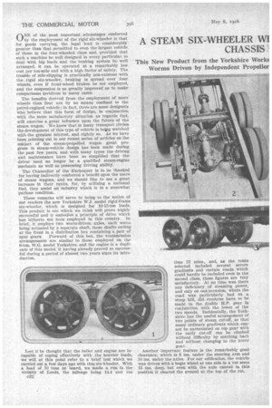
These remarks will serve to bring to the notice of our readers the new Yorkshire W.J. model rigid-frame six-wheeler, which is designed for I0-15-ton loads. This product is one which we think will prove highly successful and it embodies a pr;nciple of drive which has hitherto not been employed in this country. In brief, it employs two worm-drivenaxles, each worm being actuated by a separate shaft, these shafts ending at the front in a distribution box containing a pair of spur gears. Forward of this box, the transmission arrangements are similar to those employed on the 6-ton, W.G. model Yorkshire, and the engine is a duplicate of this model, it having already proved so successful during a period of almost two years since its introduction.
Lest it be thought that the boiler and engine are incapable of coping effectively with the heavier loads, we will at this point refer to a brief test which we carried out a few days ago with this six-wheeler. With a load of 10 tons on board, we made a run in the vicinity of Leeds, the mileage being 14.4 and the 032 time 57 mins., and, as the route selected included several severe gradients and certain roads which could hardly be included even in the second class, these figures are very satisfactory. At no time was there any deficiency of steaming power, and only on one occasion, Where the road was particularly bad on a steep hill, did recourse have to he made to the double H.P. gear in conjunction with the lower of the two speeds. Incidentally, the Yorkshire has the useful arrangement of two points of steam cut-Off, so that many ordinary gradients which cannot be surmounted on top gear with the early cut-off can be climbed without difficulty by notching back and without changing to the lower gear.
Another important feature is the remarkably good clearance, which is 8 ins, under the steering arm and 10 ins, under the axles. For our edification, the Vehicle was driven with a bogie wheel at one side in a rut some 15 ins, deep, but even with the axle canted in this position it cleared the ground at the top of the rut. At the same time we were afforded aft opportunity for noting the bogie action and measurements showed that the distance between one wheel and the bottom of the body was 13 ins., anti of the other wheel at the same side Si ins., and this Without any fouling; in fact, the difference could certainly have been exceeded.
On the road, the wagon, with its 10-ton load, gave apparently effortless running with a remarkable degree of silence, the chief noise being a slight hum from the distribution gear, the usual engine-exhaust noise being absent—a most satisfactory feature.
Before giving a detailed description of the vehicle, we will refer to the leading dimensions, which are as follow :—Overall lengt h, 27 ft; width, 7 ft. 3 ins.; height, 8 ft. 9 ins.; mean wheelbase, 16 ft. 8 ins.; bogie wheelbase, 3 ft. 8 ins.; turning circle, 58 ft, diameter; tyres, 169 mm. for 720 mm. front, 160 ram. for 850 ulna, rear, twins. The body on the vehicle we ex amined had a platform 20 ft. long and 7 ft. wide, with 4-in, rim sides. It is important to mention that this vehicle is correct as regards the amount of overhang legally permissible. Saddle tanks permit 300 gallons of water to be carried and this arrangement is designed to permit running at least 51) miles between pick-ups. The fuel-carrying capacity is 7 cwt., which, with a fully laden vehicle, is estimated to suffice for between. 100 and 120 miles.
The price will be in the neighbourhood of £1,150 with the aforementioned body.
One of the chief objects in the design of the W.I. model has been to provide a vehicle with the mechanism totally enclosed. This is one reason why chains are not employed, another being that the mu1tip1ica
tion of chains is considered by the builder to make the axles vulnerable when the vehicle is passing over loose stones ; chains also considerably reduce the clearance and are twisted when the axles tilt.
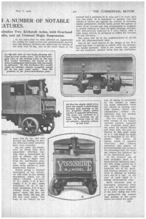
The two axles have Kirkstall casings of the forgedsteel-pot pattern, equipped with overhead worm gearing made by David Brown and Sons, Ltd., the gear reduction at this point being 41 to 1, this being the same as is employed on the W.G. model. The worms, of course, rotate in opposite directions; this reduces somewhat the degree of standardization, but presents the advantage that the turning torques are balanced up to the distribution gear.
At the forward end of each propeller shaft is a block-and-die universal joint, the dies being carried by a pin passing through the spherical end of the shaft, and location endwise of the shaft is effected by holding each end in a cup. At the rear of each shaft is a sliding block-and-die joint.
Each universal joint is thoroughly protected from the entry of dirt and water by a leather cover wired on to the joint casing and with a spring-steel clip around that portion of the cover which surrounds the shaft. Timken roller bearings are employed for the mounting of the pinions of the distribution gear.
At each side of the bogie is a long semi-elliptic spring. Each spring has slippers, that at the front end being located by an, adjusting screw as in the W.G. model, whilst the rear slipper runs on a hardened-steel slide, the material of the slippers themselves being cast
steel. The approximate length of these springs is 4 ft. 6 ins. In the centre of each is a U block, at the lower end of which, beneath the spring, is a fulcrum tube connecting the two, and pivoted to this tube are the bogie rocker arms, which have ball and cup connections to the axle casings. Each of these cups is of phosphor bronze and held in the forked end of the rocker, the rocker being closed by a detachable section of the cup held by g bolt which passes right through it and the fork. By knocking out these bolts, the axles can be withdrawn.
• It may be mentioned at this point that one of the axles has been tested on regular service between Manchester and Liverpool for a distance of 6,000 miles, the same axle running a further 6,000 miles on a fourwheeled vehicle carrying and hauling a total load of 12 tons, so that the two axles should be more than capable of coping with the loads with which they are expected to deal.
One of the reasons for the form of suspension adopted has been to provide better distribution of the stresses upon the frame. With the ordinary bogie, the whole of the rear-axle load is concentrated at the fulcrum points of the rear springs, whereas in the method employed on the new Yorkshire the springends distribute it over a much greater length_ of the frame, thus reducing the bending moment.
• One method employed for testing the strength of „ this bogie construction has been to drive the vehicle rapidly over and against kerbstones while cornering, and this has had no further effect than the bending e34 of the thick steel rims upon which the solid tyres are mounted.
On each axle. are two vertical arms with a crosspin at the top and a ball-jointed torque bar which is anchored by a universal connection to a cross-member between the axles. In the production model there will be a slight deviation from the design employed on the model we are describing, as, for the sake of neatness and to give more even distribution of the torque stresses, each of these torque members will be taken to a casting on its respective worm casing.
It will be noted that no radius rods are employed, the fixed front ends of the springs taking their place.
Very powerful brakes are provided, and these are operated by hand and foot respectively, except where wagons are to be employed in the London area, in which case power will be provided, the reason, given for this being the .danger that is caused by the ex tremely sudden deceleration often indulged in by London tramcars. Both hand and foot brakes act direct on all four wheels, and in the production model these will be compensated both between the axles and between the wheels on each axle. The braking system is extremely -simple, the main control rods being taken to levers mounted on the central fulcrum tube, from which further rods stretch forward to one axle and back to the other.
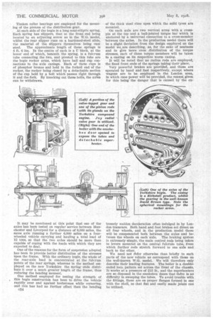
We need not 'Peter otherwise than briefly to such parts of the new vehicle as correspond with those on the well-known W.G. model. We will therefore only describe their leading features. The boiler is a doubleended loco. pattern set across the front of the chassis. It works at a pressure of 215 lb., and the superheater.3 are so disposed in the smokebox doors that there is no difficulty in sweeping the tubes. To avoid trouble with the fittings, these are on proper flanges formed in one with the shell, so that flat and easily made joints can be utilized.
'A very neat unit is formed by the engine and the two-speed gearing. The engine is of the vertical compound-balanced pattern, with a stroke of 8 ins, and bores of 4iins, and 7i ins. It develops 60 b.h.p. at a vehicle speed of 12 m.p.h. and is equipped with pistons and valves actuated by Joy radial valve gear.
A machined solid-steel stamping is employed for the crankshaft, and at the front end of this, outside the casing, is mounted the large flywheel which is one reason for the very steady running of the unit, this smoothness being assisted by the employment of a large balanceweight between the cranks. The bearings, both main and for the big-ends, are of die-cast white metal, To us one of the most interesting features of the desigh is that the lubrication is on the dry-sump principle, thus totally avoiding churning and emulsification of the lubricating oil. Two or three gallons of oil are contained in a sump, and this is drawn upon by a plunger pump driven from an eccentric on the first-speed pinion, being forced into troughs from which the oil is removed by big-end dippers. Excess oil is thrown into a gallery and led into pockets above the bearings of the crankshaft and intermediate shaft. A31 the oil is passed through a filter. The system adds greatly to the economizing of the lubricating oil.
Chassis lubrication, including the engine sump, involves the use of approximately one gallon per 750 miles, but the mechanical lubricator requires an adcli
tionaI quantity of approximately 24' gallons per 1,000 miles, the lubricant in this case being superheated steam oil.
As regards the attention required for lubrication, the sump should be inspected and, if necessary, refilled weekly. The mechanical lubricator requires attention daily, and the distribution gearbox and rear axles monthly. Grease-gun nipples are employed on the steering joints, slippers, universal joints and torquerod joints ; self-lubricating bushes are utilized for the brake camshafts. To avoid losses of lubricant the road wheels and the distribution gearing have return threads formed on brass bushes, and these have proved to be most effective.
The lbw speed in the engine-gearbox unit gives a total reduction of 12 to 1. The gears are cut in Siemens-Martin steel.
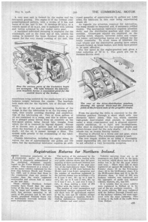
From the gearing the drive is conveyed to the distribution gearbox through a short shaft with two Hermetic fabric joints. This box, which contains high-grade heat-treated steel pinions, is supported under a stout cross-member and is situated approximately amidships. It is light and inconspicuous. Alloy steel is employed for the propeller shafts and nickel-chrome steel for the axle shafts. All the road wheels rim on bronze floating bushes.
Steering is effected by a worm and nut gear, which is totally enclosed. The Ackerman system is used.
Thu new wagon strikes us as being a thoroughly sound engineering job, and we shall be surprised if it be not afforded a very favourable reception.