


HINTS ON MAINTENANCE.
Page 32
If you've noticed an error in this article please click here to report it so we can fix it.
CONTRIBUTIONS are invited for this page from fleet managers, drivers, garage foremen, and mechanics, works staff and draughtsmen, and will be paid for on a generous scale Every system, make, and type of commercial motor vehicle is being dealt with, and the matter should be written with a view to the disclosure of workshop and garage practice in the maintenance of a vehicle.
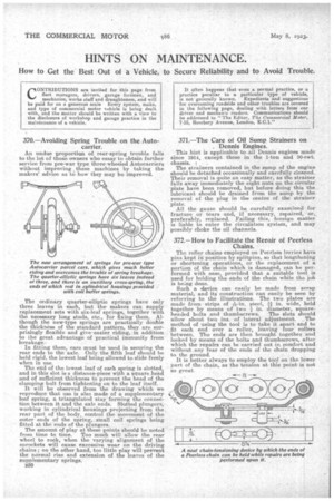
An undue proportion of rear-spring trouble falls to the lot of those owners who essay to obtain further service from pre-war type three-wheeled Autocarriers without improving .these machines by taking the makers' advice as to how they may be improved.
The ordinary quarter-elliptic springs have only three leaves in each, but themakers can supply replacement sets with six-leaf springs, together with the necessary long studs, etc., for fixing them. Although the new-type springs are practically double the thickness of the standard pattern, they are surprisingly flexible and give •easier riding, in addition to the great advantage of practical immunity from breakage.
In fitting them, care must be used in securing the rear ends to the axle. Only the fifth leaf should be held rigid, the lowest leaf being allowed to slide freely when in use.
The end of the lowest.leaf of each spring is slotted, and in this slot is a distance-piece with a square head and of sufficient thickness -Co prevent the head of the clamping bolt from tightening on to the leaf itself.
It will be observed from the drawing which we reproduce that use is also made of a supplementary leaf spring, a triangulated stay‘forming the connection between it and the axle ends. Skated plungers, working in cylindrical housings projecting from the. rear part of the body, control the movement of the outer ends of the Spring, small coil springs being fitted at the ends of the plungers. The amount of play at these points should be noted from time to time. Too much will allow the rear wheel to rock, when the varying alignment of the snrockets will cause excessive wear on the driving chains ; on the other hand, too little play will prevent the normal rise and extension of the leaves of the supplementary springs. B30
371.—The Care of Oil Sump Strainers on Dennis Engines.
This hint is applicable to Sail Dennis engines made since 1914, except those in the 1-ton and 30-cwt. chassis.
The strainers contained in the sump of the engine should be detached occasionally and carefully cleaned. Their removal is quite an easy matter, as the strainer falls away immediately the eight nuts on the circular plate have been removed, but before doing this the lubricant should be drained from the sump by the removal of the plug in the centre of the strainer plate. All the gauze should be carefully examined for fracture or tears -and, if necessary, repaired, or,, preferably, replaced. Failing this, foreign matter is liable to enter the circulation system, and may possibly choke the oil channels.
372.—How to Facilitate the Repair of Peerless
The roller chains employed on Peerless lorries have pins kept in position by splitpins, so that lengthening or shortening operations, or the replacement of a portion of the chain which is damaged, can be performed with ease, provided that a suitable tool is used for holding the. ends of the chain while the job is being done. Such a device, can easily be made from scrap material, and it construction can easily be seen by referring to the illustrations. The two plates are made from • strips ofh-in, steel, ti in. wide, held together by means of 'two in. diameter, square
headed bolts and thumbscrews. The slots should allow about two ins, of lateral adjustment. . The method of using the tool is to take it apart and to fit each end over a roller, leaving four rollers between. The ends are then brought together and locked_ by means of the bolts and thumbscrews, after which the repairs can be carried out in, comfort and without . any fear of the ends. of the chain dropping to the ground. It is better always to employ the tool on the lower part of the chain, as the tension at this point is not so great.