


Safety Scheme for Powered Brakes
Page 66
If you've noticed an error in this article please click here to report it so we can fix it.
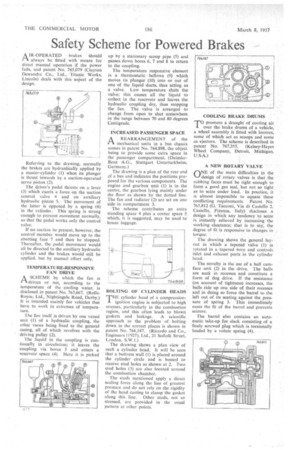
A IR-OPERATED brakes should 1-1 always be fitted with means for direct manual operation if the power fails, and patent No. 765,079 (Clayton Dewandte Co., Ltd., Titanic Works, Lincoln) deals with this aspect of the design.
Referring to the drawing, normally the brakes are hydraulically applied by a master-cylinder ( I) when its plunger is thrust inwards by a suction-operated servo piston (2).
The driver's pedal thrusts on a lever (3) which exerts a force on the suction control valve 4 and on auxiliary hydraulic piston 5. The movement of the latter is opposed by a spring (6) in the cylinder. This spring is strong enough to prevent movement normally, so that the pedal works only the control valve.
If no suction be present, however, the control member would move up to the abutting face 7 and then be stopped. Thereafter, the pedal movement would all be directed to the auxiliary hydraulic cylinder and the brakes would still be applied, but by manual effort only.
TEMPERATURE-RESPONSIVE FAN DRIVE
A SCHEME by which the fan is rAdriven or not, according to the temperature of the cooling water, is disclosed in patent No. 765,667. (RollsRoyce, Ltd., Nightingale Road, Derby.) It is intended mainly for vehicles that
• have to work in extremes of temperature.
The fan itself is driven by one vaned unit (1) of a hydraulic coupling, the other vanes being fixed to the general casing, all of which revolves with the • driving pulley (2).
The liquid in the coupling is continually in circulation; it leaves the coupling via bores 3 and enters a reservoir space (4). Here it is picked up by a stationary scoop pipe (5) and passes down bores 6, 7 and 8 to return to the coupling.
The temperature responsive element is a thermostatic bellows (9) which moves its plunger (10) into or out of one of the liquid ducts, thus acting as a valve. Low temperature shuts the valve; this causes all the liquid to collect in the reservoir and leaves the hydraulic coupling dry, thus stopping the fan. The valve is arranged to change from open to shut somewhere in the range between 70 and 80 degrees Centigrade.
INCREASED PASSENGER SPACE
A REARRANGEMENT of the
mechanical units in a bus chassis comes in patent No. 764,898, the object being to provide some extra space in the passenger compartment. (DaimlerBenz A.G., Stuttgart Unterturkheim, Germany.) The drawing is a plan of the rear end of a bus and indicates the positions proposed for the various components. The engine and gearbox unit (I) is in the centre, the gearbox lying mainly under the floor as shown by the dotted line. The fan and radiator (2) are set on one side in compartment 3.
The scheme contributes an extra standing space 4 plus a corner space 5 which, it is suggested, may be used to house. luggage.
THE cylinder head of a compressionignition engine is subjected to high stresses, particularly in the combustion region, and this often leads to blown gaskets and leakage. A scientific approach to the problem of bolting down in the correct places is shown in patent No. 766,187. (Ricardo and Co., Engineers (1927), Ltd., 21 Suffolk Street, London, S.W.1.)
The drawing shows a plan vietv of such a cylinder head. It will be seen that a buttress wall (1) is placed around the cylinder circle and is bossed to receive stud holes as shown at 2, Two stud holes (3) are also located around the combustion chamber.
The studs mentioned apply a direct sealing force along the line of greatest pressure and do not rely on the rigidity of the head casting to clamp the gasket
along this line. Other studs, not so stressed, are provided in the usual pattern at other points. T°promote a draught of cooling air over the brake drums of a vehicle, a wheel assembly is fitted with louvres, some of which act as scoops and some as ejectors. The scheme is described in patent No. 767,355. (Kelsey-Hayes Wheel Company, Detroit, Michigan, U.S.A.)
A NEW ROTARY VALVE
ONE of the main difficulties in the design of rotary valves is that the rubbing faces must be tight enough to form a good gas seal, but not so tight as to seize under load. In practice, it is almost impossible to equate these conflicting requirements. Patent No. 765,812 (G. Tacconi, Via di Castello 2, Castello, Firenze, Italy) discloses a design in which any tendency to seize is instantly relieved by increasing the working clearance; that is to say, the degree of fit is responsive to changes in torque.
The drawing shows the general layout in which a tapered valve (1) is rotated in a tapered bore and controls inlet and exhaust ports in the cylinder head.
The novelty is the use of a ball camface unit (2) in the drive. The balls are sunk in recesses and constitute a form of dog drive. If the resistance (on account of tightness) increases, the balls ride up one side of their recesses and in doing so force the barrel to the left out of its seating against the pressure of spring 3. This immediately eases the fit of the barrel and prevents seizure.
The barrel also contains an automatic take-up for slack consisting of a finely screwed plug which is torsionally loaded by a volute spring (4).