


An Unusual Two-stroke Oil Engine
Page 74
If you've noticed an error in this article please click here to report it so we can fix it.
A Resume of Recently Published Patent Specifications
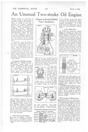
THAT progress in two-stroke oil1 engine design is going ahead is evidenced by patent No. 423,013, in which an engine of this type is described by British Continental Motors, Ltd., 150, St. Vincent Street, Glasgow, being communicated by Continental Motors Corporation, Detroit, Michigan, U.S.A. The engine illustrated operates on the single-sleeve (Burt-McCollum) system, the sleeve (3) being reciprocated and partly rotated by a wobbling crankshaft (4). A deep cylinder head is spaced away frsm. the cylinder walls to provide room for the upward movement of the sleeve.
In operation, upon the descent of the piston, the exhaust ports (1) are put into communication with the cylinder by being uncovered by the sleeve. Before the exhaust ports are reclosed, however, the inlet ports (2) are uncovered, so that there is a momentary surge of clean air. (pre
se sumably under pressure) which effectively removes all traces of the last explosion. The piston then rises, and compression and injection occur in the normal manner.
This condition is shown in the upper drawing, which illustrates also the inevitable deformation of the springs. The suggested remedy (shown in the lower drawing) consists of mounting the spring on a platform shackled to the axle in a crosswise direction. This scheme, which can be applied to both front and rear axles, is claimed to be much superior to any form of independent wheel suspension.
Using Tar-oils in Oil Engines.
IN patent No. 422,382. by DaimlerBenz A.G., of Stuttgart-Untertiirkheim, Germany, is described a modified combustion head, for enabling an oil
c50 engine to be run on heavy tar oils. The type of engine shown is that in which the fuel is injected into a precombustion chamber, and it is in the form of this chamber that the improvements are embodied.
In the drawing, which shows only the precomb usti on chamber, a conieal plug (2) is Located directly in the path of the fuel stream from the nozzle (1). The angle of this cone is the same as that of the fuel jets, so that the globules are squirted along the cone and
are thus vaporized. The gases then pass through a ring of holes (3) into the cylinder. A further feature
is the provision of an inner spaced wall (4) in the chamber, the object of which is to conserve heat and thus promote vaporization. It is also stated that the conical plug may he made of a material having a catalytic 'action.
A New Starter Gear.
AWORM and worm-wheel starting gear is described in patent No. 422,589, by E. Carmichael, of Ivy Bank, Moore, Cheshire. As shown in the drawing the starter motor carries, on a splined shaft, a worm (4) positioned between two helical springs for cushioning purposes. On the engine shaft, a worm-wheel (3) is freely mounted, engagement being achieved by irregularly spaced pawls (2), one of which, with the engine stationary, is always in mesh or about to mesh with the central ratchet-wheel (1). This ratchetwheel is not on the engine shaft, but is carried on a boss. formed on the
worm-wheel, the disc carrying the pawls (2) being the engine member. The reason for this is to allow the pawls to be thrown out of mesh by centrifugal force when the engine is running, thus freeing the whole arrangement.
One result of this is that the starter is always in mesh when the engine is stationary, which, in certain circumstances, may be of use as a parking brake. If the vehicle be left on a gradient, a forward or the reverse gear may be engaged according to the direction of slope.
Wheel-mounting on Multi-wheelers.
PARTICULARS of a wheel-mounting system to be used in connection with multi-wheeled vehicles are shown in patent No. 423,115, by W. D. Sargent, 52, Park Place, Newark, New Jersey, U.S.A. The drawing shows a beam (3) which pivots on frame brackets, and carries further longitudinal bearings (4) upon which the wheel axles are pivotally mounted. The only novel feature in the mounting appears to be the provision of resilient stops (1 and 2), the duty of which is to limit the movement of the rocking members. Further claims are made in respect of chain driving and endless tracks.