


AN INTERNAL-COMBUSTION TURBINE. .
Page 32
If you've noticed an error in this article please click here to report it so we can fix it.
A Résumé of Recently Published Patents
Many people scent to think that when we have at length achieved satisfactory designs for an internal-combustion turbine, the millennium of the automobile will be at hand. Just why this idea should exist we cannot quite'unclerstand. The steain turbine, it was prophesied, would soon sweep out of existence all kinds and classes of reciprocating &team
engines. Although that type of prirno. Mover has rittw been in satisfactory, operation for many years, we have still: to hear of the finat maker of reciprocating engines to close down his works because of competition of that nature; while, so far as the motor vehicle is concerned {although there are thousands of steam wagons in use in this country alone) we have still to hear of the first successful turbine-driven lorry.
However, it is quite possible that the introduction of a really successful internal-combustion turbine may effect considerable changes in our ideas of what should be the essential components of the motor vehicle, and it behoves us, on this page, to examine with care any inVentions of this nature which may from time to time appear.
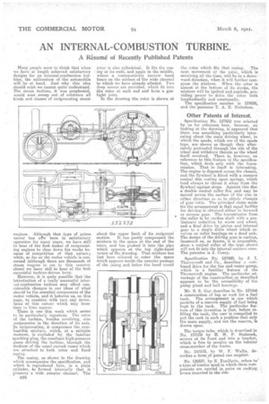
There is one this week which seems to be particularly ingenious. The rotor of the turbine, besides revolving, also reciprocates in the direction of its axis. In reciprocating, it compresses the combustible mixture' which, at a suitable moment, is exploded by the familiar sparking plug, the resultant high-pressure gases driving the turbine, -through the medium of the usual curved vanes which Are attached to both rotor and fixed casing.
The casing, as shown in the drawing which accompanies the specification, and which is reproduced here, is a plain cylinder, Ao formed internally that it presents a wide annular channel. The
C36 'rotor is also cylindrical. it fits the casing at its ends, and again in the Middle, where a comparatively narrow band bears on the surface of the wide channel to .which we have already alluded. Two deep covers are provided, which fit into :the rotor at each end and form a • gastight joint.
In the drawing the rotor is shown at about the upper limit of its reciprocal
motion, it has partly compressed the mixture in the space at the end of the rotor, and has pushed it into the pipe which appears at the top right-hand 7orner of the drawing. That mixture has just been allowed to enter the space which appears inside the annular passage of the zaaing and below the band round
the rotor which fits that casing. The next movement of the rotor, which is revolving all the time, will be in a downward direction, when it will further compress the mixture. When the rotor is almost at the bottom of its stroke, the mixture will be ignited an explode, previding power to drive the rotor bath longitudinally and rotationally.
The specification number is 157630, and the patentee T. A. E. Nicholson.
Other Patents of Interest.
Specification No. 157552 was selected by us for reference here, because, on looking at the drawing, it appeared that there was something particularly interesting about the main driving wheel, in which the spuds, which are of the spade type, are shown as though they alternately protruded through the rim of the wheel and withdrew therein as the wheel itself revolved. There is, however, no reference to this feature in the specification, whioh deals only with the transmission. That in itaelf is interesting. The engine is disposed across the chassis, and the flywheel is fitted with a concave conical disc resting upon springs, which tend always to thrust it away from the flywheel against stops. Against this disc a double cord-Cal roller fits, and may be moved across the surface of the Use in either direction so ;s to obtain changes of gear ratio. The pririciPar claim made for the arrangement 25 that equal facility for driving is obtained either in forward or reverse gear. The tranatbission from the roller is by cardan shaft with a preliminary reduction by worm aad wheel, and a final drive by pinion and internal gear to a single drive wheel which revolves on roller bearinsa on a dead axle. The design of the driving gear is curious, inasmuch .as, as drawn, it is impossible, since a conical roller of the type shown will not fit into the internal concave cone. The patentee is J. Coney.
Specification No. 157480, by J. I. Thornyereft and Co., describes a combined drive for the fan and water pump, which is a familiar feature of the Thornycroft engine. The particular advantage of the construction as described appears to be the accessibility of the pump gland and ball bearings. .
Mr. S. S. Guy describes in No. 157566 a construction of tap or cock for a fuel tank. . The arrangement is one which: permits of a reserve supply of fuel being kept in the tank. The particular feature of this invention is that, before refilling the tank, the user is compelled to put the cock in such a position that only the main supply, and not The reserve, is drawn upon.
The torque tube, which is described in No. 157559 by H. H. P. Seabroak, screws at its front end into a bracket, which is free to revolve on the tubular cross-member of the frame.
No. 157575, by W. F. Wallis, describes a form of petrol can emptier.
-No. 130337, by E. Feuillette, refers to a type of tractor spud in which these cornponents are carried in pairs on rocking 'a levers mounted in the rim.