


With Intent to Improve.
Page 22
If you've noticed an error in this article please click here to report it so we can fix it.
A Weekly Summary of Recent Patents, of Interest to the Maker and User of Commercial Motor Vehicles,
Selected and Abridged by H. S. Hall, A.M.I.A.E.
A Carburetter Patent.'
Jules Fagard, of 147, Corporation Street, Birmingham, suggests in patent No. 103627, an improvement on carburetters of that type in which a pilot jet is used for starting or slow running, this jet receiving its fuel from a well which is open to the atmosphere. Those readers who are acquainted with the construction of the Zenith carburetter will realize the type to which reference is made. Usually in such carburetters,
the size of the pilot jet is proportioned to meet fuel requirements.
The modification suggested by this inventor is to supply the fuel to this independent chamber by moans of a jet having a fairly large opening, and so dis• posed that its upper or delivery end is a short distance only below the normal level of the fuel, and is, moreover, above the opening to the passage leading to the induction pipe. The drawing which we reproduce shows one of several methods of attaining this end. It will be seen by examination-.that the reserve of fuel available to the pilot jet is determined by the height (II).
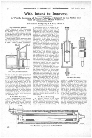
A Paraffin Vaporizer.
Cogn Constantinesco, of the Haddon Engineering Works, Honeypot Lane, Alperton, has patented an improved type of vaporizer for heavy hydro-carbons, such as paraffin, the object being
to enable such fuels to be utilized in engines normally designed to burn petrol. This invention relates to that type of vaporizer in which the fluid is gasified by being allowed to trickle over heated surfaces or heat-accumulating bodies. Experience has shown that with such vaporizers, when the fuel is vaporized in the presence of air, there is a oritical temperature, which varies according to the fuel used, at which the process is completely disturbed by a secondary process °Wow combustion, rendering the gas produced unsuitable'for use in internal-combustion engines. A previous patent by the same inventor, No. 2870 of 1912, describes a process whereby in such a vaporizer fuel is vaporized in the absence of air. The difficulty which occurred in that case was that the process was comparatively a slow one. The pre-: sent invention has as its principal object the attainment of more rapid vaporization. It consists of a vaporizer in which. the vaporization takes place in a through current of exhaust gases from an internalcombustion engine, the fuel percolating through heat-accumulating bodies, air being excluded from the vaporizer. Reference to the illustration will show the general arrangement of the device. The exhaust crases enter by the top pipe shown at the left-band side of the drawing; they travel through the vaporizer, which also serves as a silencer, along the outermost annular space, also through the central tube, and make their exit at the extreme right-hand end of the contrivance. Most of the heat from these gases is imparted to the mass of rivets or similar material which is indicated on the drawin,. The fuel is provided through the float chamber on the left, and enters the vaporizer by means of the long perforated tube shown; thence it trickles over the heated rivets and is carried to the engine through a delivery pipe not shown on this drawing. Exhaust gas enters the vaporizer by the passage at the right, the amount being regulated by the valve shown.
For Ease of Starting.
W. McGavin Smellie, of 38, Lygen Road, Edinburgh, explains in specification No. 103,564 his invention for supplying a combustible mixture to a petrol engine for quick and ready starting. It
consists of a hand or foot-operated pump centrally disposed in a cylinder, the cylinder Serving as a container for the petrol. A U tube is disposed within this cylinder, having one of its upper ends open, the other end leading to a small supply pipe. A small hole in the bottom of the U allows of the entry of petrol, another hole is situated opposite the inner end of the supply pipe. Pressure on the pump handle causes a current of air to be forced through the supply fuel, which air will, of course, gather a certain amount of fuel in the course of its passage The air thus gathered is forced through. the U tube, taking with it some petrol, and this mixture of carburetted air and petrol is delivered to the induction pipe through a special form of spray tube.