


A ROTARY SLEEVE-VALVE ENGINE.
Page 28
If you've noticed an error in this article please click here to report it so we can fix it.
A Resume of Recently
Published Patent Specifications.
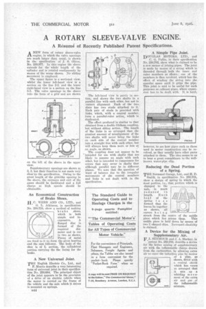
A NEW form of rotary sleeve-valve 1-1. engine, in which the valve openings are much larger than usual, is shown in the specification of J. S. Oliver, No. 250,877. In this engine the sleeve extends for the whole length of the 'cylinder and is 'rotated continuously by means of the worm shown. No sliding movement is employed.
The upper figure is a sectional view, whilst the lower left-hand view is a section on the line 2-2, and the lower • right-hand view is a section on the line The valve openings in the sleeve take the 'form of a grid andare shown on the left of the sleeve in the upper view.
Supplementary openings are shown at 3, 3, but their function is not made very dearin the specification. Owing to the great length of the grid-like opening in the sleeve, the entrance and exit of the gases should be facilitated and a full charge at high speeds should be obtainable.
An Economical Construction of Brake Shoes.
H.C. WEBB AND CO., LTD., and G. L. Atkinson, in specification No.: 250,724, show a method, of making brake ,shoes, which is both simple and in
expensive. A flanged disc is formed of the
required diameter and is cut in two as shown. Pieces of metal gre fixed to it to form the pivot bearing and the cam follower. The body of the shoe is of L section the cylindrical )ortion carrying the the lining for the brake.
A New Universal Joint. T HE English Electric Co., Ltd., and F. Morris describe a very interesting form of universal joint in their specification No. 250,684. The principal object of the joint appears to be the provision
• of a drive of an electric vehicle when the motor is carried on the frame of the vehicle and the axle which it drives is mounted on springs.
B44 The left-hand view is partly in seelion, and shows the two shafts in a parallel line with each other, but not in correct alignment Each of the two discs has two studs attached to it. Each pair Of studs is provided with links, which, with a central member, farm a parallel-ruler action; which is duplicated. The effect•produced is similar to that obtained from a double Oldham coupling, but without skiing action. The length of the links is so arranged that the greatest amount of misalignment of the two shafts will never bring the links an each side of the central member into a straight line with each other, but will always keep them more or less at an angle, as shown.
The coupling does not appear to be intended for use with shafts that are likely to assume an. angle with each other, but is intended to compensate for errors that may occur in shafts that although parallel may be in different planes. We note that the question of want of balance due to the irregular movements of the central members and links is not dealt with in the specification.
For the convenience of Principals, Fleet Managers and Engineers, Salesmen, Freight Agents and others, the Tables are also issued in a form convenient for the
pocketbook. Please specify "Pocket-Book Form" when so required_ • A copy will be sent FREE ON REQUEST to the Editor," The Commercial Motor," 7-15, Rosebery Avenue, London, E.C,1. • A Simple Pipe Joint.
DOUGLAS MOTORS; LTD., and
0.G. Pullin, in their specification No. 250,702, show what is claimed to be anew means of joining pipes. The joint is made by meansof a string which is threaded through both the inner and outer members as shown ; one of the members is then revolved, which has the. effect of winding the string into the annular space until it grips the pipe. This joint is said to be. useful for such purposes as exhaustpipes, Where expansion hits to be dealt with. It is hard;
however, to see bow pipes such as those nsed in motor construction can be revolved, as they usually have other parts attached to them. The idea seems to us to bear a great resemblance to the wellknown water-pipe clip.
Reducing the Dead Portion of a Spring.
THE Normand Garage, Ltd., and H. D. Smith', in specification No. 250,781, show a design of spring in which the dead portion, i.e., that portion which is clamped to the axle, is much reduced in length. Each
le a f of the spring i s s o formed that the leaves lie together as shown, all curves being struck from the centre of the saddle
piece which lieS across them. This saddle piece is held down by means of two U-shaped clips. Increased elasticity is claimed.
A Device for the Mixing of Supplementary Mr. F.J. SEYMOUR and f. A. Mackay, in patent No. 250,788, describe a device for the better mixing of supplementary air with the inflammable charge drawn from the carburetter, by allowing .extra air to enter the induction pipe by means of a pipe, as shown, fitted with a conical shield which hag vanes so arranged that it sets up a whirling m o v ement of the extra air and gas. of the inflammable mixture.