


Patents Completed.
Page 30
If you've noticed an error in this article please click here to report it so we can fix it.
Complete specifications of the following patents will be sent to any address in the United Kingdom upon receipt of eightpence per copy at the Sale Branch, Patent Office, Holborn, W.C.
CLUTCH PEDALS.—Watts and Another.—No. 24,464, dated 21st October, 1910.—According to this invention there is applied to clutch pedals a device for permitting only the proper use of such mechanism. A dash pot employing either a vacuum or compressed air or both is arranged behind and connected to the clutch pedal so that the operation of the latter is controlled by the dash pot. When the pedal is depressed and is required to engage the clutch, the foot is simply removed from the pedal and a spring brings the clutch into engagement at a slow rate controlled by the dash pot. A convenient construction is that in which the cylinder is pivoted to the dashboard and the piston rod is similarly pivoted to the pedal. The exhaust holes for the air in the dash pot are preferably arranged in a helical line.
SPEED INDICATOR.—Benz and Roe, No. 10,750, dated 2nd May, 1910.—In this specification there is described a speed indicator which gives an audible warning when a certain predetermined speed is reached A central shaft is driven at a speed in proportion to the speed of the vehicle and this shaft carries on it an arm to which is hinged a bell clapper ; when the speed of the vehicle exceeds a certain limit the centrifugal action Oil this
arm causes it to rise, and ,the clapper strikes the gong. In order to prevent the gong's operating at a low speed owing to the jolting of the vehicle, a controlling arm is .attached above the clapper arm, hanging at a more acute angle to the vertical axis. 'this arm engages the lower arm and prevents its rising until the speed is sufficient to raise the upper arm clear of the lower one.
CHANGE-SPEED GEAR.—Herbert and Vernon.—No. 21,262, dated 13th September, 1910.—This invention relates to change-speed gears of the type in which a number of toothed wheels or belt pulleys are mounted freely upon the shaft and are arranged to be clutched thereto by a moveable key or similar device carried within the shaft. The main difficulty hitherto experienced with this form of gear has been to provide sufficient and good bearings for the various members owing to the short length of the bearings and the presence of keyways which reduce the bearing surface and render the loss of lubricant very easy. According to the present construction, each member is mounted on a ball or roller bearing carried on the shaft so that there is a space between the bearings for the action of the movable key. The shaft is slotted for the passage of a spring key, which is provided with bevel edges and is adapted to drop into notches in the centre of the gear members. The face of each gear member is recessed near the centre to receive the outer races of the ball bearings, the inner races of the bearings are fast on the shaft and they strengthen it so as to prevent its expanding under the stress of driving.
TAXIMETER,—McKenna (Post Lock Register Co.).—Nn. 21,030, dated 9th December, 1910,—rn this specification there is described a means for preventing that kind of fraudulent use of a taximeter, whereby the vehicle is occupied and no corresponding registration is made, A frame is hinged on the front partition, and it falls down, blocking the doorway, on to the front of the seat. Suitable spikes or a serrated edge are employed to make the prevention even more effective. This frame is connected by suitable means to the taximeter flag, so that, when the frame is raised, the taximeter is put into operation.
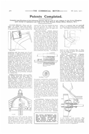
FRICTION COUPLING. — Daimler Motoren Gesellschaft, No. 11,337/10, dated under International Convention 26th November, 1909.—This invention relates to clutches of the type in which two friction cones are reversely arranged and are axially movable in reverse directions into engagement with their co-operating surfaces. In the construction illustrated the driving shaft, on the left, is in alignment with the driven shaft, on the right ; on the driven shaft there is keyed and alidably mounted a sleeve. The left-hand inner clutch member is fast on this sleeve, and the right-hand inner clutch member is keyed to and longitudinally movable on the sleeve also. Two rings with suitable ball bearings are arranged, one on the left controlling the axial movement of the adjacent clutch member, and one on the right foot on the sleeve and thereby controlling the axial movement of the further clutch member. The clutch is disengaged by these two rings' being forced apart by a toggle joint operated from a foot pedal. Springs normally hold the clutch in engagement.