


A POTPOURRI OF INTERESTING PATENTS.
Page 30
If you've noticed an error in this article please click here to report it so we can fix it.
A Résumé of Recently Published Specifications.
THE Alvis Car and Engineering Co., Ltd., can, at the very least, claim the merit of simplicity for the spring damper which they describe in patent specification No. 216,451: A plain flat bar is freely suspended from a bracket on the main frame of the chassis. On the spring, near the axle, is a bracket which is faced with some non-metallic friction-engendering material. To this bracket there is a cap, also faced with the same material, and cap and bracket are united by a bolt't under the nut of which is a large flexible spring washer designed to allow for a little adjustment of the pressure between the bracket and cap, between which slides the flat bar suspended from the chassis. The operation of the device will be apparent from the foregoing description. As the chassis rides up and down on the springs, the plate or bar is caused to slide up and down between the two pads of friction material, damping the movement of the spring in proportion to the pressure exerted by the spring washer. The patentees point out that this device can easily and cheaply be fitted to existing motor vehicle .chassis.
SPECIFICATION No. 216,414 refers to a sprag or ratchet gear to be applied when there is some risk of a vehicle running backwards out of control. 'The mechanism embodies a lever conveniently placed in the driver's cab. A coupling rod from that lever connects it to a short lever on the end of a shaft which carries a gearwheel. This gearwheel is in engagement with another, and on the spindle on which the second gearwheel, is mounted is a cam. The cam controls a pavvl which, when in the lower position, engages ratchet teeth on the brake drum of the vehicle; when in the upper position it is free from that ratchet. The gearing is contained within a case, which is supported on the cover for the brake drum. There does not appear to be any, reason, and none is given in the specification, why the first short lever to which the main hand lever is coupled should not operate the pawlactuating cam direct.
OZONIZING the inlet air to the car buretter is the method which is referred to, by M. Kristensen de Trairup, as a means of improving the efficiency of internal-combustion engines. A series of spark gaps is placed in the ht. leads, one to each plug. All the gaps are arranged together in a casing, and the inlet air to the carburetter is enriched by ozonized air, which is drawn from this chamber. Windows are fitted in the casing within which the spark gaps are situated, so that their operation may be seen, and means are provided for adjusting the size of the gap. The specification in which this invention is described is No. 216,373.
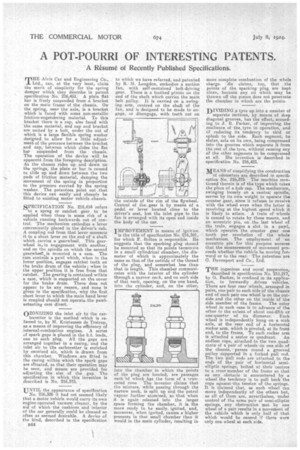
UNTIL the appearance of specification No. 216,386 it had not seemed likely that a motor vehicle would carry its own engine-operated vacuum cleaner, by the aid of which the cushions and interior of the car generally could be cleaned so often as seemed desirable. A device of the kind, described in the specification 844 to which we have referred, and patented by R. M. Langdon, embodies a suction fan, with self-contained belt-driving gear. There is a toothed pinion on the end of the shaft which carries the main belt pulley. It is carried on a swinging arm, centred on the shaft of the fan, and is designed to be made to engage, or disengage, with teeth cut on the outside of the rim of the flywheel Control of the gear is by means of a pedal or lever located close to the driver's seat, but the inlet pipe to the fan is arranged with its open end inside the body of the car. .
IMPROVEMENT in means of ignition is the title of specification No. 216,391, for which F. Bolton is responsible. He suggests that the sparking plug should be mounted so that its points terminate in a small cylindrical chamber, the diameter of which is approximately the same as that of the outside of the thread of the plug, and somewhat less than that in length. This chamber communicates with the interior of the cylinder through a narrow neck, and on each side of that neck, opening, on the one hand, into the cylinder, and, on the other, 'nto the chamber in which the points of the plug are located, are passages each of which has the form of a truncated cone The inventor claims that the mixture, while passing through the narrow neck, is split up and the petrol vapour further atomized, so that when it le again released into the larger space forming the chamber, it is the more ready to, he easily, ignited, and, moreover, when ignited, causes a higher pressure in that small chamber than it would in the main cylinder, resulting in more complete combustion of the whole charge. tie claims, too, that the points of the sparking plug are kept clean, because any oil which may be thrown off the piston does not penetrate the chamber in which are the points.
DIVIDING a tyre up into a number of
separate sections, by means of deep diagonal grooves, has the effect, according to J. B. Parker, of improving the resilience of the. tyre in operation, and of reducing its tendency to skid or splash to, the side. Each segment, he states, acts on its own, being compressed into the grooves which separate it from the rest of _the tyre, without causing any of the other segments to be compressed at all. His invention is described in specification No. 216,421.
MEANS of simplifying the construction of odometers are described in specification No. 216,375. The machine mentioned therein is of the type which takes the place of a hub cap. The mechanism, swinging loosely on a central spindle, serves by its own weight to operate the counter gear, since it refuses to revolve with the wheel even when the latter is revolving at the highest speed which it is likely to attain. A train of wheels is caused to rotate by these means, and an eccentric pin, on the last wheel of the train, engages a slot in a pawl, which operates the counter gear one tooth per revolution of the whole mechanism. The employment of an eccentric pin for this purpose ensures that the measurement of movement proceeds whether the vehicle be moving forward or to the rear. The patentees are G. Davenport and Co., Ltd.
THE ingenious and novel suspension, described in specification No. 215.217, by G. Barker, is confined in its application, to forwardly driven vehicles. There are four rear wheels, arranged in pairs, one pair to each side of the Chassis and of each pair one wheel is on the outside and the other on the inside of the side member of the frame. The outer wheel in each rose is in advance of the other to the extent of about one-fifth or one-quarter of its diameter. Each wheel is independently hung on a stub axle, at the rear end of a horizontel rocker arm, which is pivoted, at its front end, to the frame. To each rocker arm is attached a sector or quadrant. An endless rope, attached to the two quadrants of a pair of wheels on one side of the chassis, passes round a grooved pulley supported in a forked pull rod. The two pull rods are attached to the ends of the pair of horizontal semielliptic springs, bolted at their centres to a cross member of the frame so that as any obstacle is encountered by a wheel the tendency is to pull back the rope against-the tension of the springs. It is claimed that, as each wheel can move independently of the others but, as all of them are, nevertheless, under control of the same pair of semi-elliptic springs, any obstruction met by one wheel of a pair results in a movement of the vehicle which is only half of that which would be caused if there were only one wheel at each side.