


An Aid to Injector Inspection
Page 58
If you've noticed an error in this article please click here to report it so we can fix it.
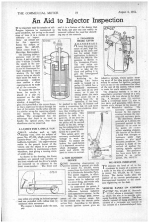
I T is important that the nozzles of oil engine injectors be maintained in good condition, but owing to the small sizes of bore it is a matter of some difficulty to inspect them. An optical aid for this operation forms the sublject of patent No. 647,337, which comes from L Hartridge, Buckingham.
The drawing shows a pictorial view of the device. A pair of adjustable V-blocks (1) holds the nozzle in the correct alignment, so that it can be illuminated by light emanating from a window (2), the light source being an electric bulb inside the body. A microscopic eyepiece then enables a close examination to be made of all the externals.
To inspect the interior bores, the nozzle is placed in a clip (4) mounted on the side adjacent to another window. A magnifyingglass (5) is provided at the correct focus, so that a sight can be taken through the bore of the nozzle. On the other side (6) is a similar set-up for inspecting closedend nozzles having side delivery orifices. The arrangement has the advantage that there is no need to handle the optical parts, thus their cleanliness can be preserved.
A LAYOUT FOR A SMALL VAN
QMALL vehicles, such as light D., delivery vans, form the subject of patent No. 673,111, which comes from Daimler-Benz A.G., Stuttgart-Unter7 turkheim, Germany. The improvements reside in the general layout of the vehicle and the ob.ject is to promote manceuvrability by maintaining a short wheelbase, thus giving a turning circle of sinall radius.
As shown in the drawing, the frame members are carried well forward of the front wheels and the driver's pedals are mounted on or adjacent to the front cross-member. The front and rear axles arc sprung on helical springs and are provided with radius rods to constrain their movement.
The engine is located under the seat, a40 and it is a feature of the design that the body, cab and seat can readily be removed without the need for disturbing any of the controls.
A TWO-SPEED BRAKE LEVER
A HAND-BRAKE Z-1 lever that gives two ratios of pull, high for taking up the slack and low for actual brake application, is shown in Patent No. 668,116. The patentee is Berliet et Cie, Venissieux, France. The two ratios are selected by pushing the lever to take up the slack and pulling it to give the lower-geared braking force.
Referring to the drawing, t h e brake cable is wound on a pulley (1) which has a composite movement; it can turn on its own centre, or it can be swung about the main lever pivot (2) on a
rocking lever (3). In operation, if the lever be pushed to the left, its bottom end works a connecting link (4) and turns the pulley in an anti-clockwise direction, thus winding up the slack in the cable. This position is held by a pawl (5). If the lever be then pulled to the right, the pulley will be carried bodily to the left, swinging the rocking lever with it, the whole being maintained by a pawl (6).
This action gives the necessary mechanical advantage to work the brakes. To release the brakes, the push-button (7) is depressed, an action which disengages both pawls and allows the parts to return to normal.
A NEW IGNITION DEVICE QOME interesting observations on sJignition systems in general are made in patent No. 671,033, which comes from the Centre National de la Recherche Scientific, Paris. The patent suggests, in effect, that the conventional ignition system with its induction coil is a poor thing, and works only on account of its defects.
To understand the patent, it is necessary to appreciate the difference between inductive and capacitative current. In the first, the voltage peak occurs ahead of the current surge, but in the second case the current pulse arrives first. According to the patent, the normal ignition system gives an inductive current, which causes burning away of the plug points and which would be useless for ignition purposes were it not for the condenser-like effect of the rest of the system, which tends to make the spark capacitative.
The proposed remedy is to use a capacitative generator instead of a coil, and this is the item shown in the drawing. A two-part rotor (1) revolves inside a cylindrical stator (2), also in two parts, and generates, when driven, intense static charges in the manner of the old Wimshurst machine. The necessary condenser is formed by the capacity existing between the running and stationary parts.
The distributor, shown generally at 3, directs the generated current to the terminals (4) as soon as the points (5) come within sparking distance. The interior of the device is filled with nitrogen or hydrogen under high pressure to give good dielectric properties. No mention is made of the method of sealing the running spindle against leakage. The generator has been more fully described in an earlier patent, No. 643579.
01L-LEVEL INDICATOR
T°indicate the level of oil in the crankcase by means of a pointer on a scale, is the aim of a scheme shown in patent No. 673,624, by IT. Laury, France. The device works after the manner of an electric petrol-gauge, a float-operated resistance in the crankcase registering on the dash.
VEHICLE BANKS ON CORNERS DATENT NO. 673,608 (C. Bancroft, / U.S.A.) shows a passenger vehicle in which the aim is to provide automatic banking on corners. The. four wheels, instead of being placed at the corners of a rectangle, are located at the corners of a diamond-shaped base.