


Two-speed Hydraulic Brake Cylinder
Page 50
If you've noticed an error in this article please click here to report it so we can fix it.
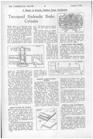
TH E design of an hydraulic brake with two effective operating rates forms the subject of patent No. 587,099 by H. Page, Alhambra, California, U.S.A. The aim is to provide a light, fast-moving force for bringing the shoes to bear, followed by a more powerful thrust for the actual braking
The drawing shows the expander used in the scheme. It incorporates a pair of opposed pistons, each formed with a small diameter (I) and a larger portion (2). The smaller pistons are fitted with spring-loaded ball valves (3), which, under increased pressure, will unseat and pass the fluid through radial ports into the larger cylinders.
In operation, fluid pressure arrives at the central point and forces apart the two smaller pistons, at the same time raising a slide valve (4), which cuts off , a port (5). The pistons travel fast until they are arrested by drum Contact.
The pressure is then increased by continued application, the ball valves are forced from their seats, and the larger pistons are thus brought into action for the main effort. On the return stroke, fluid from the larger cylinders cannot return via the ball valves, and so an escape is provided by port 5, which is reopened when the slide valve descends. While the smaller pistons are operating, vacuum in the larger cylinders is prevented by fluid from entering past a check valve (6).
THREE-VALVED OIL ENGINE
FROM experts in the design of small oil engines, W. Spoor and F. Perkins, Ltd., 17 Queen Street, Peterborough, comes patent No. 587,276. It deals with improvements in combus
tion arrangements. The aim is to obtain an intimate intermixture of the fuel and the air by turbulence created by offset inlets.
The engine described is provided with two inlet and one exhaust valve, all located in the cylinder-head. They are placed at approximately 120 degrees apart around the cylinder bore, the injector being located on the cylinder A40 axis. The injector gives a four-jet spray, thejets being 90 degrees apart.
The drawing shows a section across the two inlet valves and a scrap view portray a modification.
A common passage serves the two valves, and one may be shrouded by a lip (1). Both are operated in unison by coupled overhead rockers. The combustion chamber has a toroidal outline, and is machined out of the top of the piston.
Both the combustion cham b e r and the shroudirp; lip are produced by machining instead of casting, so that uniformity of performance can reasonably be expected from the several units of a multi cylindered engine. The injector is co-axial with the piston.
MAKING LARGE PLASTIC PANELS
AMETHOD of forming large plastic panels, such as might be used in vehicle bodywork, is shown in patent No. 587,282 by the Ford Motor Co., Ltd., 88 Regent Street, London, W.1.
In the drawing, I is the finished article and 2 the set-up before the moulding operations. The panel is built from what is popularly called " rag-plastic," that is, layers of fabric impregnated with resin. The cores are the main subject of the patent; these consist of fabric (3) rolled around Cellophane tubes (4), the latter being filled with sand or fine metal shot.
After the hot-pressing operation the filling is removed, leaving a hollow structure. The filling must possess " give " so that the moulding pressure will be uniform. The panels thus produced are said to be stronger than hardwood, although they are only a little over half the weight.
SACK-LOADER FOR LORRIES
COMING from F. Crisp, L. Powell and Brooks (Mistley),. Ltd., Manningtree, Essex, patent No. 587,296 gives details of a loading attachment for vehicles. The apparatus is intended chiefly for loads in small units such as sacks.
The lifting device consists of a framework including a pair of upright channels (I) in which runs a roller journalled carriage (2). A cable is attached to the carriage, taken over the top and then back to the middle, where it emerges and runs to a wind.ng drum (3). The latter is power-driven and braked, the control lever being shown at 4.
A cable (5) enables the lever to be operated if necessary from the rear end. In action, a load of sacks is put on the carriage, and taken to the upper limit, where it can be removed by an operator. The lifting gear is not attached to the vehicle, but provision is made for stowing it on the crossmembers when not in use.
FORMULA FOR ANTI-FREEZE
A SUGGESTION for a new antirAfreeze mixture comes in patent No. 587,229 from W. Levenson, Drexel
Hill, Pennsylvania, U.S.A. Its chief feature is that it will not solidify until a temperature of minus 40 degrees C. is reached.
The ingredients are sodium nitrate, which is made into a saturated solution (at room temperature) and potassium nitrite. The latter is added to the solution until it again reaches saturation. The resulting mixture is claimed to be without deleterious action on iron, aluminium, copper and zinc, and any alloys of those metals.