


Carburetter with Emulsifying Economy Device
Page 34
If you've noticed an error in this article please click here to report it so we can fix it.
A Résumé, of Patent Specifications That Have Recently Been Published ACARBURETTER claimed to give a high degree of economy is shown in patent No. 537,531 by Vauxhall Motors, Ltd., Kimpton Road, Litton,
and others. The basic principle is that of mixing a small quantity of air with the fuel passing from the jet, This occurs only at part-throttle openings, however; at full throttle no extra air is admitted.
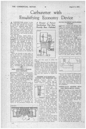
..In the drawing, which shows a section of the main choke tube, part 5 is a chass-bar in the tube containing thebrifices for admitting fuel ihto tl_e air-strewn via passage 6. In. the main well, from which this.passage is fed; is a sliding tube (3) having a metering orifice at the bottom, and a series of fine holes (2) at the. top, for_ ths admission of air. This tube is interconnected with the throttle (4) so that it descends as the throttle is opened.. When the throttle is fully „open, as drawn, the tube (3) is closed off from the atmosphere by a sealing washer on a shoulder (1). At all other positions of the 'throttle a certain amount of air is drawn through the fine holes (2) and forms an emulsion with the fuel in -passage 6. The carburvtterhas the usual compensating and idling jets, and is provided with an accelerating pump.
WIDE-ANGULARITY TRAILER • BALL COUPLING
I NTENDED chiefly for tractor-trailer
towing connections, a ball-and•
• • socket mechanism of the quick-release type is shown in patent No. 537,500 by A. Wall, 9, Buckingham Mansions, London, N.W.6, and H. Golding, 107, Sirdar Road, London, N.22.
The ball itself is trepanned away to leave an off-centre pin (4) on which. the drawbar end (3) pivefs; the movement so permitted being additional to that given by the turning of thei ball, the idea being to afford an increased angle of deflection without " necking " the drawbar in the vicinity of the ball. The quick-release mechanism comprises four radially slidable jaws (2), formed on their inner faces to fit the ball, and grooved on the outside to accommodate retracting. springs (5). The jaws are moved in or out by a handle attached. to a cam-plate (1) which, by one movement actuates the jaws, and thus opens or closes eie
hoving. Further deflection of the drawbar is permitted by the ability of any one of the font jaws to move radially, independently of the others, for a limited distance. This is achieved by allowing clearance in the slot of the cam-plate, but it is of impfirtance that the movement thus permitted be considerably less than that required' to release the ANOTHER ELECTROSTATIC CLEANER FOR PRODUCER GAS
rROM Vauxhall Motors, Ltd., Kimpton Road,. Luton, and D. Foster, comes in patent No. 537,448, a design for an electrostatic filter for producer gas. The patent refers to the electrical circuit only, of which we include a diagram.
It embodies a .step-up transformer operated' bythe vehicle accumulator. The primary, circuit (1) 'contains a vibratory interrupter (5) which may be worked by the iron of the transformer core, like the trembler of an electric bell. In the secondary circuit there is a thermionic valve (2) for rectification, the output from which charges a condenser (3) connected across the terminals of the cleaner tube (4).
A claim made for the device is that it is of especial value in removing tar, after, the larger impurities have been filtered OWL by more simple means: '
DEVICE TO CHECK VALVE-SPRING SURGING
HIGIILY stressed coil springs, such as valve springs, may at certain frequencies develop a surging motion, that is, a zone' of over-compression may oscillate up and down the spring and produce local overload. Although this motion is far too rapid to be seen by eye, it may nevertheless be the cause of apparently inexplicable failures.
To prevent it is the ohylk.t of a scheme, shown in patent No. 536,967 by G. Salter and Co., Ltd., and J. Babhe, both of la, 'High Street, West Bromwich, illustrated on this page. The usual valve-spring (2) abuts• against a stop collar (1) which ,rests upon a shoulder on the valve-guide. Behind the collar is a secondary spring (3)• which is normally inactive, though it exerts a force against the collar. This is approximately equal to the opposing force of the main spring, when the
atter is in its position'of lightest load.
Should the main spring start to surge, however, there is a moment in the surging cycle when its pressure on the stop collar is reduced. When this occurs, the secondary spring moves the collar and momentarily shortens the main spring, thus tending to damp out the oscillations.
COPPER-ALLOY BEARING WITH• -THIN WHITE-METAL LINING BEARING alloys of the copper-base L./type, whilst fairly durable, are more liable to damage the crankshaft,in the event of lubrication failure than are the 'softer white-metal type. An attempt to combine the good features of both is shown in patent No. 537475 by Cleveland Graphite Bronze Co., Cleveland, Ohio, U.S.A.
It is suggested that use be made of a steel-backed copper-alloy bearing, faced with a very thin layer of white .metal, not more than 0.0075 in. thick. This thickness should .irot be exceeded, but it may be reduced to 0.001 in.
These proportions, it is claimed, give a bearing which, whilst possessing the strength and fatigue-resistance of a copper-alloy hearin& at the same time
• has the low sbaft-wearing. properties of a white-metal bearing. In the event of the white metal being completelY worn through, the shaft will continue to run satisfactorily on the copper. p