


PATENTS SUMMARIZED.
Page 22
If you've noticed an error in this article please click here to report it so we can fix it.
Two New Rotary Internal Combustion Engines.
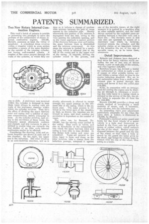
This week's batch of patents is notable as presenting two ,attempts to solve the problem of the-construction of rotary internal combustion engines. 116,536, Bertelli, possesses at least the virtue of simplicity. A cylindrical drum revolves within a chamber which in cross section resembles a square of the same diameter as the outside of the rotating cylinder, but haying well-rounded corners. A number of flat vanes project'through the walls of the cylinder, in which they are tree to slide. A stationary cam mounted within the cylinder is designed to keep these vanes always in contact with the walls of the stationary chamber within which the cylinder revolves. They have the effect of dividing the space between rotor and casing into a number of separate compartments, mainly triangular in form. As the cylinder revolves, and owing to the movement of these vanes, the triangular spaces alternately contract and expand, and this variation in size is utilized to enable what are virtually the four strokes of an Otto cycle internal combustion engine to be effected. Considering the drawing, inlet and exhaust branches are shown at each end of the chamber. On the right, the upper one is the induction. The rotor revolves in an anti-clockwise direction, and as it does so it induces 'a change of combustible mixture between the pair of vanes nearest to the induction pipe. Shortly afterwards this portion of the mixture is segregated from the rest, owing to the vane passing the induction opening, and as the vanes approach 1,narrow portion of the clearance between rotor and casing, the space between them is diminished
and the mixture compressed. At this stage the -mixture is ignited by a sparking plug which is situated just to the left of the centre and in. the upper wall of the casing. It expands, driving the cylinder round in the process, and
shortly afterwards is allowed to escape through the upper passage on the lefthand side of the casing, which is the exhaust pipe. ' The same process is followed in the lower part of the chamber, so that, as drawn, the impulses are delivered in pairs, and their number per revolution is dependent on the number of vanes.
The other one, by Remand, No. 116,601, has the moving vanes carried in the casing. They serve as valves, and also as boundaries of the compartment into which the space between rotor and casing is from time to time divided. In this design both casing and rotor are cylindrical. Vanes are secured to the rotor, taper in form,' and these, as the rotor revolves, take a charge from the induction passage, compress it against
one of the movable vanes; at the right moment it is ignited by a sparking plug or other suitable method, and the rotor driven onward by the exploded gases expanding between a movable vane and a fixed one.The movable vanes in this case also are operated by means of a stationary cain which is, however, mounted outside the cylinder; and the patentee claims as an important feature of his invention the use of two sets of movable vanes, or, as he terms them, abutments.
• Detail Improvements.
Roberts and Johnson have designed a final drive for heavy vehicles which embodies .the use of two sets of driven wheels, a pair on each side of the vehicle, and close together (116,537). .
Hamilton-Grapes has devised a heater for carburetted air which is really-a coil of copper or other suitable tubing carried within a casing which is'closeAo tho engine induction manifold. Hot air • to the carburetter taken from a muff on the exhaust pipe is passed through this easing and serves to beat the coiled pipe (116,542).
Kelly, in connection with an arrangement for cooling the, engine case by drawing air through it, interposes a revolving disc with vanes in a casing which is situated in the airway of the fan the object-.being to separate the oil from the air (116,564).
Barrett (116,568) provides a cheap and simple method of introducing a small quantity of steam, and-, if necessary, extra air also, into the induction pipe.
An interesting Valve gear adjustment particularly adaptable for use when the valve stem is hollow, is illustrated in 116,656, by Hagens.
Puttergill's combined safety guard and brake for the front wheels of a motor vehicle is a light steel framework attached to the front axle but guided by means of rubber rollers. which" embrace the rim of the wheel. Rubber stops are disposed between the guard and the rim of the wheel, so that when a body is struck by the guard the latter gives to the shock, an,d brings the rubber stops in contact with the rim of the wheel, thus acting as a brake.